13
11/2026
Wiring Door, Leak, Smoke, and Temp/Humidity Sensors to a Smart PDU System
A technical guide to wiring BM-CGQ07 door, BM-CGQ06 leak, BM-CGQ04 temp/humidity and BM-CGQ05 smoke sensors into a smart PDU, with supply, signal and documentation checks.
Wiring Door, Leak, Smoke, and Temp/Humidity Sensors to a Smart PDU System
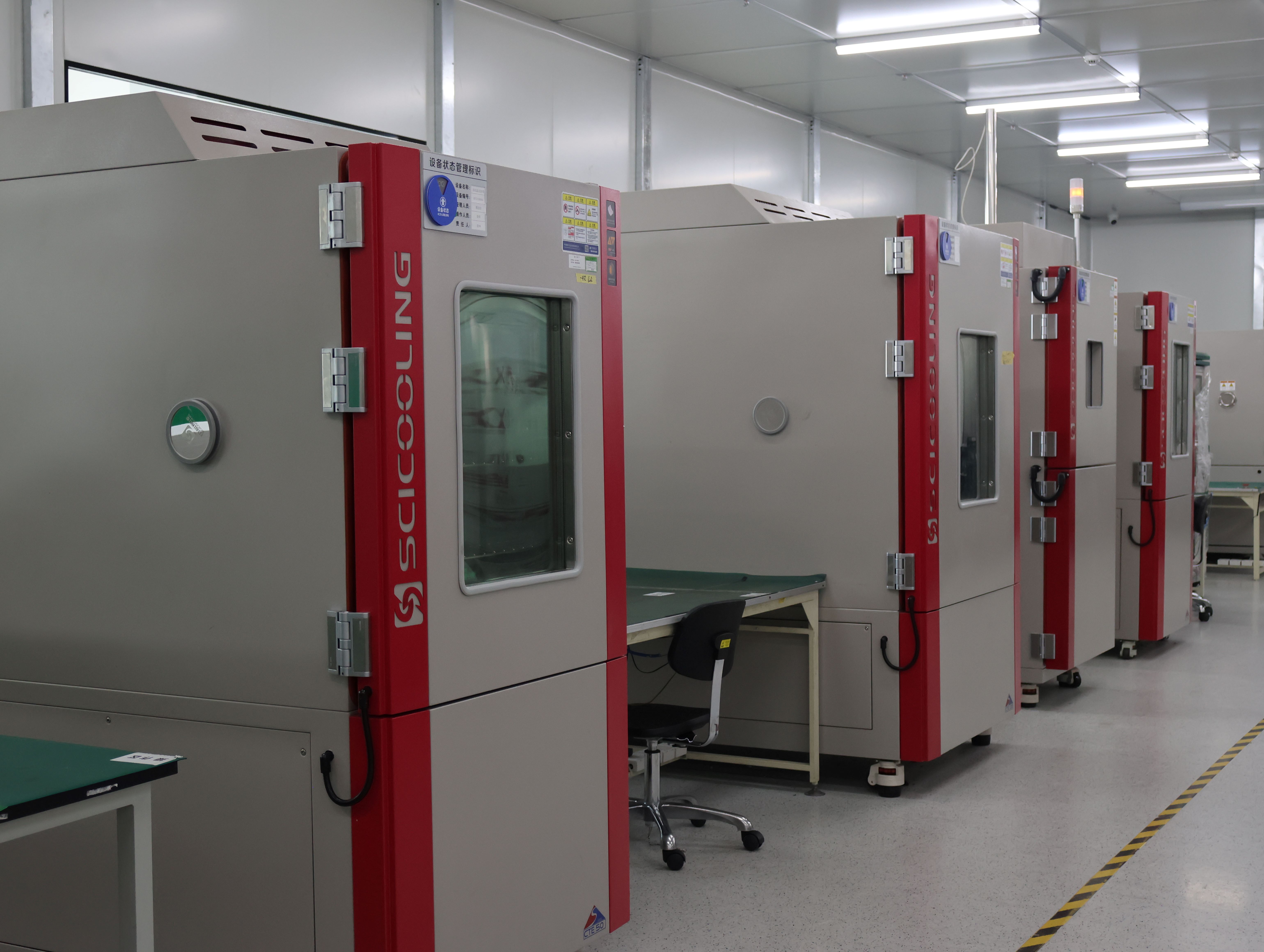
High-low temperature test chamber used during hardware verification. Environmental data is only useful when the sensing hardware behind it has itself been validated.
Four sensors, two signal classes, three verification checks. That is the operating logic behind wiring a door contact, a water leak detector, a temperature and humidity sensor, and a smoke detector into a smart power distribution unit (PDU). The BM-CGQ07 door sensor reports as a dry contact with configurable NO/NC behaviour. The BM-CGQ06 water leak detector is powered by 12 V DC and communicates over RS-485 Modbus. The BM-CGQ04 temperature and humidity sensor measures across 0–100% RH. The BM-CGQ05 smoke detector accepts a 10–35 V DC supply.
Everything around those four facts has to be read from documentation rather than assumed from a product name: how many discrete inputs the controller exposes, which serial port carries the Modbus bus, whether an auxiliary DC rail exists at all, and what the controller treats as an alarm state. Wiring errors in sensor installations rarely come from the cable; they come from a specification that nobody verified in writing before the rack was built.
BOMPDU is the brand of Wuxi Bom Electronic Technology Co., Ltd., a Wuxi, Jiangsu-based manufacturer of intelligent rack power distribution units established in 2018. The company holds ISO 9001:2015 quality management system certificate 05126Q03324R001, issued by NOA Testing & Certification Group Ltd., with a scope that covers the design and development of intelligent PDU control boards and core control boards for water level sensors. This guide is written for the stage where a rack design has already been evaluated and is about to be executed: electrical engineers, commissioning technicians, and procurement teams who need the environment layer to be documented, wired, and signed off without a second site visit.
The four wiring facts this article is built on
- Dry contact (BM-CGQ07): a two-state device. The NO/NC setting decides what a broken cable looks like to the controller.
- RS-485 Modbus (BM-CGQ06): an addressable device on a 12 V DC supply. It needs an address, bus discipline, and a register map.
- Humidity and temperature (BM-CGQ04): a measurement spanning 0–100% RH. Probe placement changes the reading more than the sensor does.
- Smoke (BM-CGQ05): a 10–35 V DC device. The supply must be confirmed inside the cabinet, not assumed from a datasheet family page.
One boundary is stated up front: this article does not describe controller internals, port counts, register addresses, or power budgets for any specific PDU model. Those values differ by model and must come from the supplier's datasheet, wiring diagram, and Modbus map. What follows is the documentation and wiring discipline that makes those documents usable.
The Problem: Power Telemetry Without Physical Context
A smart PDU answers the question how much electricity is moving. It does not, on its own, answer what physically happened in the cabinet. Socket-level monitoring exports current, voltage, energy, and power per outlet — a capability documented in deployed projects such as the 800-unit installation at an airport data center in China, where each socket reports those four values in real time. That telemetry is precise and it is also blind to four failure modes that carry no electrical signature until the moment they cause one.
| Physical event | Why power data misses it | Detection layer |
|---|---|---|
| Cabinet door left open | Containment is breached while load stays normal | BM-CGQ07 dry-contact door sensor |
| Water under the raised floor | First electrical symptom is a trip or a short | BM-CGQ06 leak detector on RS-485 Modbus |
| Smoke inside the cabinet | Particles arrive before the temperature rise does | BM-CGQ05 smoke detector, 10–35 V DC |
| Humidity drift | Load is unaffected; ESD and condensation risk are not | BM-CGQ04 temperature and humidity sensor, 0–100% RH |
The recurring failure pattern in integration projects is assumption. A buyer specifies a network managed PDU, assumes the controller exposes four dry-contact inputs, one RS-485 port, and a 12 V DC auxiliary output, and discovers on installation day that one of the three is missing or differently rated. The cable is correct, the sensor is correct, and the project still slips, because the supply and input inventory was never written down.
Industry Background: Why Environmental Sensing Moved Into the PDU
Environmental monitoring used to be a separate appliance with its own network drop and its own dashboard. Market data explains why it has been absorbed into the rack power device instead.
ResearchAndMarkets' PDU industry research, published in November 2024, reports that intelligent PDUs accounted for 55% of total PDU market revenue as of 2023 — the smart segment is the majority of the revenue base, not a premium niche. MarketsandMarkets projects the global data center PDU market to reach USD 14.23 billion by 2032, and projects the intelligent PDU segment growing at a CAGR of 19.5% from 2026 to 2032. These are source-reported forecasts and should be treated as planning context rather than as procurement evidence for a specific model.
The compliance backdrop is equally relevant to a sensor installation. IEC 62368-1:2023 is the safety standard applied to ICT and AV equipment, including PDUs, in most major jurisdictions, according to IECEE/IEC. Any device added inside the cabinet — including a 12 V DC leak detector and a 10–35 V DC smoke detector — sits within the electrical environment that standard is concerned with, which is why power provisioning for sensors belongs in the technical file and not only in the installer's head.
The practical consequence for buyers is a shift in specification habit. A data center PDU is now evaluated on what it can collect and export, not only on breaker rating and outlet count. That makes environmental inputs a line item in the RFQ, and makes the exact input inventory something the supplier must state in writing.
The Detailed Solution: Four Sensors, Two Signal Classes
The sensor set splits cleanly into two integration classes, and the class determines the wiring discipline far more than the sensor function does. Dry-contact devices are state-based: the controller sees open or closed. RS-485 Modbus devices are addressable: the controller sees a device that answers queries. The first class is wired, the second is configured.
BM-CGQ07 Door Sensor — Dry Contact with Configurable NO/NC
The BM-CGQ07 reports as a dry contact, which means it introduces no voltage of its own: it closes or opens a circuit that the controller interrogates. The configurable NO/NC option is the part that carries real engineering consequences, because it defines how the sensor behaves when the wiring itself is damaged.
In normally-closed configuration, the contact is closed while the door is shut. Opening the door opens the circuit and produces the alarm. A cut cable produces the same open-circuit condition, so a severed wire looks like an alarm rather than like silence — that is the fail-safe choice. In normally-open configuration, the contact closes on door opening. A cut cable then reads as a closed door, which is the fail-visible trade-off: fewer nuisance alarms, less protection against a broken conductor.
Two checks belong in the commissioning script before either configuration is locked in. First, confirm from the controller documentation which input state is interpreted as the alarm condition, and whether the input can be inverted in configuration. Second, decide whether a short delay is needed: a door opened for a 20-second service task and a door left open overnight are the same electrical event, and only a delay separates them.
BM-CGQ06 Water Leak Detector — 12 V DC over RS-485 Modbus
The BM-CGQ06 is the only sensor in this set with two distinct wiring domains: a 12 V DC power pair and an RS-485 Modbus communication pair. That separation matters at the design stage. The 12 V DC pair must come from a supply whose voltage, current capability, and polarity are confirmed for this device. The Modbus pair must follow bus practice: a unique slave address per device on the segment, consistent A/B polarity, termination at the physical ends of the bus, and the baud rate, parity, and register map taken from the device documentation rather than guessed.
Leak detection is a placement problem before it is a wiring problem. Sensing cable or probe points belong at the lowest practical point of the enclosure, under raised floor tiles in the immediate cabinet footprint, and near known condensate paths. Coverage should exclude areas where routine cleaning water flows, because a detector that alarms during floor cleaning is a detector that gets disabled within a month.
The Modbus route also gives the option to latch. A leak event that self-clears the moment the floor dries will disappear from the log before the on-call engineer opens the dashboard; a latched event stays visible until a human acknowledges it. Confirm from the documentation whether latching is a device setting, a controller setting, or a monitoring-platform rule — the answer differs by architecture.
BM-CGQ04 Temperature and Humidity Sensor — 0–100% RH
The BM-CGQ04 measures across the full 0–100% RH span. That range is what makes the device useful in an uncontrolled space, but it also means the number it reports has to be interpreted rather than merely displayed. Low relative humidity raises electrostatic discharge risk around sensitive assemblies; high relative humidity raises condensation risk on cold surfaces. The threshold band that matters is a site policy decision, and it should be written into the alarm configuration with an explicit source, not chosen by feel during commissioning.
Placement dominates reading quality. A probe at the cold-aisle intake measures the air the equipment is about to draw in, which is usually the control variable. A probe at the exhaust measures the result. Mounting next to a CRAC discharge vent, against the PDU exhaust, or on the door leaf itself will produce values that are technically correct and operationally misleading. Rate of change is often more informative than the absolute value: a cabinet that gains humidity quickly after a door-opening event is telling you something about the room, not just about the sensor.
BM-CGQ05 Smoke Detector — 10–35 V DC Supply
The BM-CGQ05 accepts a supply between 10 V DC and 35 V DC. The wide window is convenient, not automatic: the first task is to confirm what DC voltage is actually available in the cabinet and that the available supply falls inside that window with the correct polarity. Without that confirmation, the device is specified but not qualified.
Mounting follows the manufacturer's instructions and the applicable local fire code, and within those constraints airflow decides performance. A smoke chamber has to be exposed to the air path that would carry combustion products; a detector tucked behind cable bundles or mounted outside the hot air stream can be correctly wired and still slow to respond. Alarm handling also deserves an explicit decision before installation: a smoke event that only writes a log line is not a response plan. Determine which notification path is acceptable in the destination facility and document it, rather than assuming a downstream action exists.
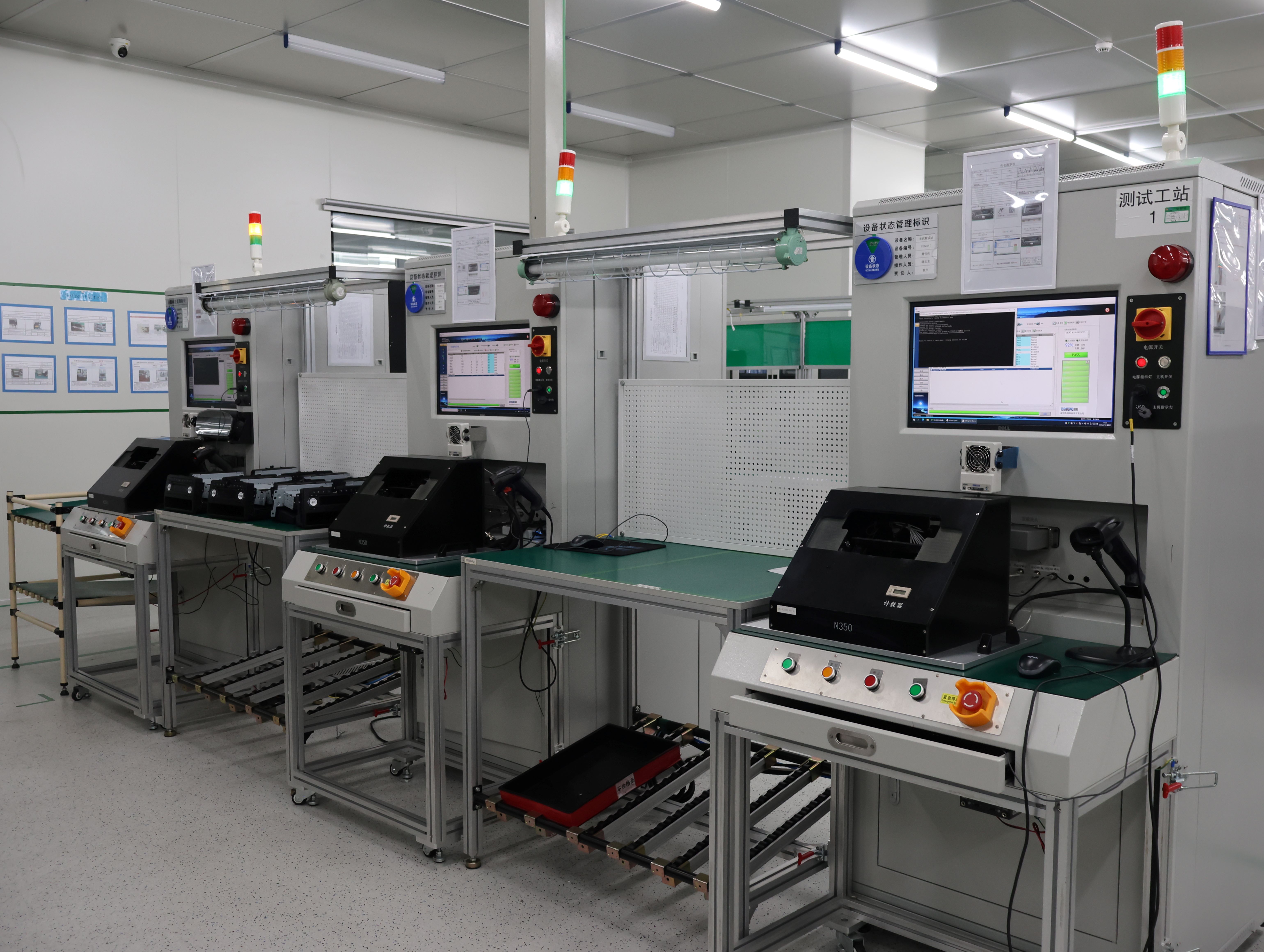
Testing station for control-board verification. BOMPDU performs 100% testing on all products as part of its quality control process.
What the PDU Must Provide — and What Must Be Documented
This is the point where the article returns to the boundary stated at the start. The required controller capabilities are a specification list, and every line on it has to be answered in writing for the exact model under consideration.
- The number and type of dry-contact inputs, and whether those inputs are supervised or unsupervised.
- The presence of an RS-485 port, the supported protocol on that port, and the maximum number of devices permitted on the bus segment.
- Whether an auxiliary DC supply is available for sensors, at what voltage, with what current budget, and through which connector.
- Whether the platform presents environmental values and power values in the same view, or requires a second system.
- Which alert channels are supported for threshold events.
Threshold alerting across power and environmental events is well established in the commercial market: Raritan's technical specifications for its intelligent rack PDUs state that alerts can be sent via SNMP, email (SMTP), and syslog when predefined power or environmental thresholds are exceeded. That is a useful reference point for what a technical RFQ should ask for — not a claim about any other manufacturer's controller.
The practical deliverable to request with the quotation is a document pack: datasheet for the exact model, terminal assignment table, wiring diagram, and — for the Modbus device — the register map. A supplier who can produce all four has done this before. A supplier who cannot has just moved the discovery to installation day.
Step-by-Step Breakdown: From Fault List to Signed-Off Commissioning
The sequence below is ordered so that a decision made late never invalidates a document produced early.
Step 1 — Write the fault list before choosing hardware
List the physical events the site actually cares about: door open beyond a set interval, water at the cabinet base, smoke in the cabinet, relative humidity outside an agreed band, and temperature above an agreed limit. Each entry becomes a monitoring point with an owner. Points without an owner become alarms nobody answers.
Step 2 — Assign a signal class to every point
Door events map to a dry contact. Leak detection in this set maps to RS-485 Modbus. This classification is what determines whether commissioning time goes into wiring or into configuration, and it sets expectations for the installer's electrician.
Step 3 — Verify supply compatibility as a documented fact
Two sensors in this set carry explicit supply requirements: the BM-CGQ06 at 12 V DC and the BM-CGQ05 at 10–35 V DC. Confirm the source of that DC supply, its polarity, and its capacity under load. If the PDU does not provide it, provision an appropriately rated supply inside the cabinet and record the part number, its rating, and its protection device in the technical file.
Step 4 — Get input compatibility in writing
Do not accept "sensor ready" as an answer. Ask for the count of dry-contact inputs, the RS-485 port assignment, the supported protocol, and the device limit per bus. Put the answers in the RFQ response and compare them against the fault list from Step 1.
Step 5 — Route and separate cabling
Keep sensor wiring physically clear of AC feeds and PDU output cables, which is standard practice for any low-voltage signal run. Allow service loops at both ends so a door leaf can swing and a shelf can slide without straining a conductor. Label runs at both ends and record the route on the as-built drawing while it is still visible.
Step 6 — Address and name every point
For the Modbus device, assign a unique slave address and record it against the physical location. Use a naming convention that survives staff turnover, for example rack-and-position plus sensor type plus index. The alarm label an operator reads at 03:00 should identify a cabinet, not a channel number.
Step 7 — Configure thresholds and alarm behaviour
Set the door delay, the humidity band, the leak latch decision, and the smoke notification path agreed in Steps 1 and 3. Decide alarm routing and escalation at the same time: a custom alarm threshold PDU is only as useful as the routing configured behind it. This is also the moment to confirm which state each dry contact reports in normal operation, so that "closed" on the dashboard means what the operator assumes.
Step 8 — Commission, test, and hand over
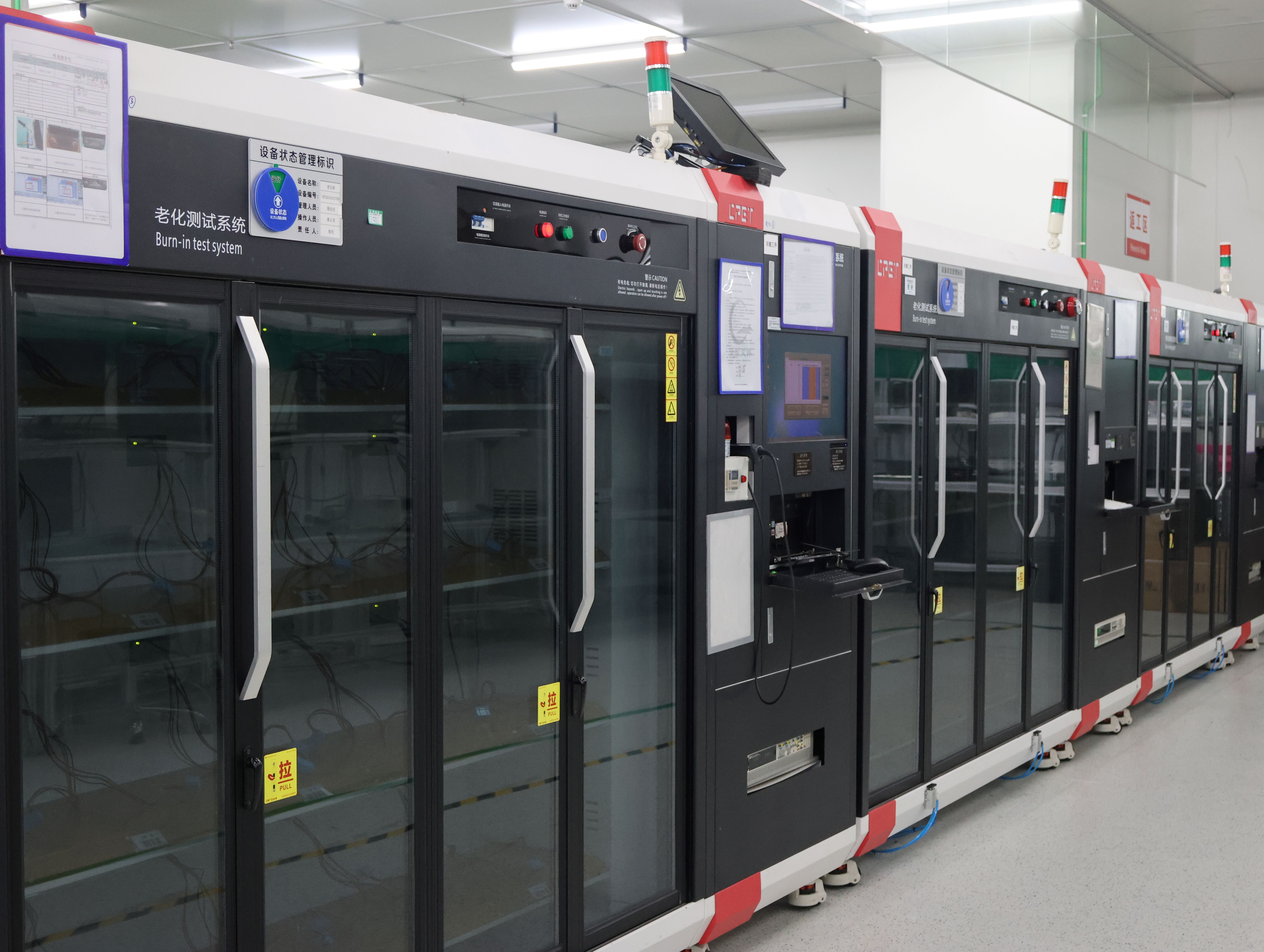
Burn-in test system. Verifying assemblies on the production side reduces the number of unknowns the commissioning technician has to chase on site.
Test each point physically and record the result. Open and close the door with the contact in its configured state. Trigger the leak detector at its sensing point using the manufacturer's specified method. Test the smoke detector using its approved test method rather than by introducing combustion products into a live rack. Cross-check the humidity reading against a reference instrument. The handover pack should contain the as-built drawing, the point register with addresses and labels, the alarm test log, and the original datasheets for all four devices.
Use Cases: Where a Sensor-Instrumented Rack Pays for Itself
Two published deployments show the power-side foundation that environment monitoring is normally added to. Both are power telemetry projects, and the distinction matters: the case data describes power monitoring, not an environmental sensor installation.
Airport data center, China — 800 units. This installation monitors electricity usage with real-time monitoring of current, voltage, energy, and power for each socket, and has operated stably for three years. In a facility of that shape, where cabinets are distributed and access is controlled, the economics of an added door and leak layer are straightforward: a door-open alarm that reaches the right person replaces a physical inspection trip, and a leak alarm at the cabinet base arrives before the electrical symptom does.
Data center server manufacturer, China — 2,000 units. This deployment supports server aging tests, with remote on/off control, real-time monitoring, and unmanned on-site operation, and has operated stably for two years. Aging and burn-in areas are exactly where smoke and temperature monitoring complement power data: the room is designed to run hot and to run unattended, which is the combination that makes early particle detection worth wiring.
A third pattern is the industrial smart PDU installed outside a classic white space — a production hall cabinet with dust, wash-down proximity, and vibration. There, the leak detector and door contact carry most of the value, because the failure modes are environmental before they are electrical. The sensor choice does not change; the threshold policy and the mounting do.
Where the cabinet is small and remote, the same set supports an edge deployment: one network managed PDU reporting power and environment over a single management path, with a remote control PDU function allowing an outlet to be cycled without travel. Where several cabinets share a management architecture, a cascadable master-slave PDU arrangement can reduce the number of management addresses per row — but the device count, topology, and controller requirements must be specified exactly, because published cascading figures in the market are not defined consistently (see the comparison table below).
Comparison Tables
Table 1 — The four sensors at a glance
| Model | Function | Supply | Signal / output | Configuration decision |
|---|---|---|---|---|
| BM-CGQ07 | Door open / closed | None (passive contact) | Dry contact, NO/NC configurable | Which state equals alarm; delay value |
| BM-CGQ06 | Water leak detection | 12 V DC | RS-485 Modbus | Slave address, baud and parity, latch rule |
| BM-CGQ04 | Temperature and humidity | Confirm per datasheet | Humidity measurement across 0–100% RH | Probe position; humidity band source |
| BM-CGQ05 | Smoke detection | 10–35 V DC | Confirm per datasheet | Cabinet supply within window; notification path |
Where a cell reads "confirm per datasheet", the value was not asserted here on purpose: the device documentation for the exact variant is the only acceptable source.
Table 2 — Dry contact versus RS-485 Modbus integration
| Dimension | Dry contact (BM-CGQ07) | RS-485 Modbus (BM-CGQ06) |
|---|---|---|
| Information returned | One state: open or closed | Register values defined by the device map |
| Consumes on the controller | One discrete input per point | One address on a shared bus |
| Wiring discipline | Two conductors, route and label | Power pair plus bus pair; polarity, termination, addressing |
| Broken-cable behaviour | Depends on the NO/NC setting chosen | Device stops responding — visible as a communication fault |
| Commissioning effort | Mostly physical | Mostly configuration and documentation |
Table 3 — Published third-party reference points and how to read them
| Published specification | Source | What to verify before relying on it |
|---|---|---|
| PDU-to-PDU cascading up to 16 devices | Raritan intelligent rack PDU technical specifications (2025) | Exact topology and counting method; controller requirement |
| Up to 50 devices daisy-chained on a single IP address | Vertiv Intelligence Director documentation, PowerIT rack PDU brochure (2026) | Not directly comparable with the 16-device cascading figure — the architecture and counting definition differ |
| IPv4/IPv6 management, SNMP v2/v3, Modbus/TCP | Raritan intelligent rack PDU technical specifications (2025) | Whether IPv6 support is mandatory in your network; treat it as a separate RFQ field |
| ±0.5% metering accuracy on PRO4X models | Server Technology product overview (2026) | Test conditions and measurement basis are not published in the excerpt — request the test report |
Table 3 is included for one reason: sensor integration is often specified alongside management features, and a IPv6 supported PDU requirement or a cascading requirement is frequently assumed rather than written down. Reading the published figures side by side also shows why "50 devices" and "16 devices" cannot be treated as the same metric. The same caution applies to power-path features such as sequential power-on PDU behaviour or a single/three phase switchable PDU input configuration: these must be stated for the exact model in the project datasheet, not inferred from a product family name.
FAQ
Which documents should be verified before wiring sensors into a smart PDU?
Verify three layers. The supplier layer: Wuxi Bom Electronic Technology Co., Ltd. holds quality management system certificate 05126Q03324R001, issued by NOA Testing & Certification Group Ltd. to GB/T 19001-2016/ISO 9001:2015, valid from 2026-07-24 to 2029-07-23, with a scope covering design and development of intelligent PDU control boards and core control boards for water level sensors. The software layer: the Intelligent 2nd generation PDU product carries computer software copyright registration 2024SR1888355 from the National Copyright Administration of the People's Republic of China. The deployment layer: IEC 62368-1:2023 is the safety standard applied to ICT and AV equipment, including PDUs, in most major jurisdictions. Ask for the datasheet, terminal assignment table, wiring diagram, and Modbus register map for the exact model in the same request.
Can the PDU and sensor set be customized for a specific rack layout?
BOMPDU offers OEM and ODM production services, with customization covering IP and 3P input configuration, outlet number, and meter and control features. All products undergo 100% testing as part of the quality control process. Environmental monitoring details — how many sensor points a cabinet needs, how long the cable runs are, and which alarm logic applies — belong in the project datasheet and wiring diagram, and should be confirmed in writing against the exact model before the order is released.
What drives the budget for a sensor-instrumented rack?
Four drivers dominate: the number of monitored points, the cable routes and lengths, the level of customization, and the testing scope required before shipment. Published commercial terms for BOMPDU are a minimum order quantity of 2 units, a typical lead time of 30 days, and a monthly production capacity of 1,000 units. Because the sensor points are the variable that scales fastest, fixing the fault list before the RFQ is the most effective cost control step available to a buyer.
Can I validate the wiring on a small quantity before scaling?
Yes. A minimum order quantity of 2 units allows a small validation batch to be built, wired, and tested before a larger release. Every product is 100% tested, and remote support is available as after-sales service for commissioning questions. A validation batch is the right place to confirm the NO/NC behaviour of the door contact, the Modbus address and register behaviour of the leak detector, and the humidity reading against a reference instrument.
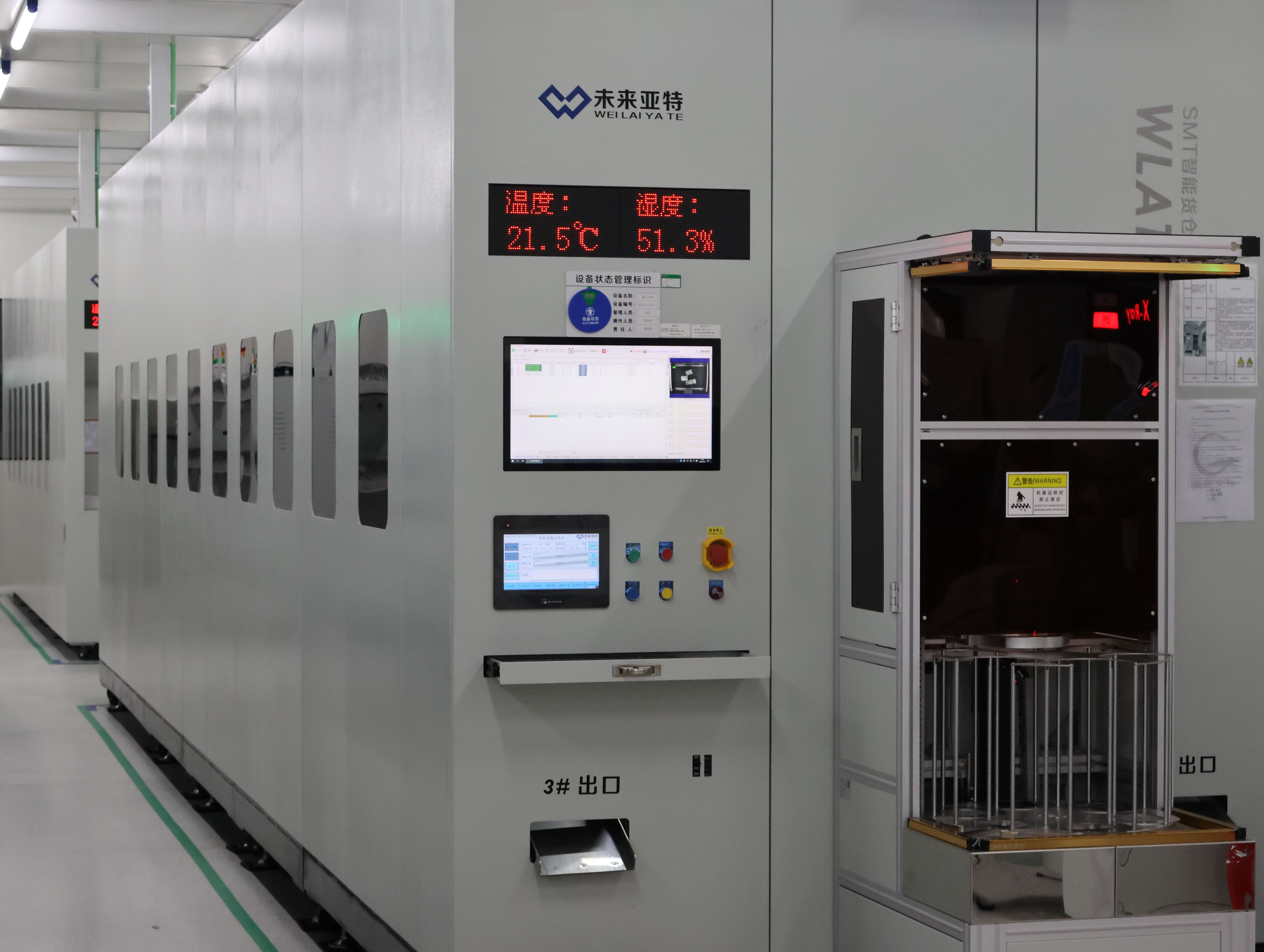
Smart warehousing supports staged shipment for pilot quantities and full rollouts.
What is the typical lead time and production capacity?
Typical lead time is 30 days, with a monthly production capacity of 1,000 units, and remote support provided as after-sales service. For a project with a fixed commissioning window, request the lead time in writing with the purchase order and tie the delivery milestone to the document pack — datasheet, wiring diagram, and register map — so the installation team receives specifications before the hardware arrives.
Conclusion
Wiring four sensors into a smart PDU is not a difficult job once the three checks are treated as mandatory. Signal class first: a dry contact returns a state, an RS-485 Modbus device returns register values, and the two demand different commissioning work. Supply second: the BM-CGQ06 needs 12 V DC, the BM-CGQ05 accepts 10–35 V DC, and both need the source confirmed inside the cabinet rather than assumed from a family datasheet. Documentation third: input counts, port assignment, protocol support, and register maps all have to be stated for the exact model, because a controller specification that nobody wrote down is a specification nobody can install against.
The sensors themselves are the simple part. The BM-CGQ07 with configurable NO/NC decides how a broken cable appears to the monitoring platform. The BM-CGQ04 spans 0–100% RH and rewards careful placement. The BM-CGQ06 adds addressable leak detection over Modbus. The BM-CGQ05 adds particle detection on a wide DC input window. Together they close the gap between knowing how much power is moving and knowing what happened in the cabinet — which is the difference between a dashboard and an operational control.
Next step: check the wiring documents against your rack layout
BOMPDU (Wuxi Bom Electronic Technology Co., Ltd.) builds intelligent rack PDUs and supports OEM/ODM projects with customization of IP and 3P input, outlet number, and meter and control features. Ask for the datasheet, terminal assignment table, and wiring diagram for the exact model, then validate the sensor wiring on a pilot quantity.
- Email: tony1091803@wxbom.cn | Tel: +86 18751550927
- WhatsApp: +1 (786) 989-2761
- Website: www.wuxibom.com
- Product catalogue: download the BOMPDU brochure (PDF)

Quality management system certificate 05126Q03324R001, issued by NOA Testing & Certification Group Ltd., valid 2026-07-24 to 2029-07-23.
Third-party figures cited in this article are attributed to their publishers: ResearchAndMarkets PDU industry research (published November 2024), MarketsandMarkets data center PDU market report, IECEE/IEC for IEC 62368-1:2023, and the respective manufacturer technical documentation for Raritan, Server Technology, and Vertiv. Model-specific controller capabilities must be confirmed in writing for the exact product being purchased.