18
11/2026
When a Rack Alarm Fires: A Smart PDU Troubleshooting Scenario for Power vs. Environment Faults
A step-by-step Smart PDU triage sequence for rack alarms: verify power measurements first, then isolate temperature, humidity, leak, smoke and door causes.
When a Rack Alarm Fires: A Smart PDU Troubleshooting Scenario for Power vs. Environment Faults
When a rack alarm fires, the useful first question is not what failed, but which measurement produced the alarm. A Smart Power Distribution Unit reports on electrical behaviour it measures at its own input and outlets. An environmental chain reports on temperature, humidity, water, smoke and door state through separate sensors. Deciding which of those two domains an alarm belongs to determines who responds, what they bring, and whether a remote action is safe. The triage order below puts power first, environment second, and treats the combination of alarms as the real evidence.
This is a scenario walkthrough for data center and cloud operators, and for the buyers and engineers who specify rack power. It follows one rack through a single ambiguous alarm, then shows how the same logic adapts to telecom, command-center, industrial and roadside installations. Product details come from BOMPDU's published specifications; the scenario itself is an illustrative example, not a report of a specific customer event.
The scenario: two alarms on one rack, at the same minute
Consider a conditional example. A cloud rack in a twelve-rack row carries a mix of compute and storage. Overnight, a network-managed PDU raises a current alarm on one output branch, and at almost the same time the room's environmental monitoring reports a high temperature reading near the top of the same rack. Nothing else in the row is alarming. The on-call operator has three options: dispatch an electrical engineer, dispatch a facilities engineer, or take a remote action from the monitoring console.
Choosing badly costs time in both directions. Sending a power engineer to a cooling problem wastes the best window; resetting an outlet that feeds a device into an overheating condition can make matters worse. The sequence that follows reduces that uncertainty in the order the evidence actually becomes available.
Why power and environment alarms so often arrive together
Two mechanisms explain most co-occurring alarms, and neither requires a fault in the PDU.
- Load produces heat. Electrical load in a rack becomes heat inside the rack. When a device is commissioned or a workload shifts to another server, current and temperature can rise together while every component behaves as designed. The power alarm is real, and the environment alarm is a consequence.
- Cooling loss appears as temperature first, and sometimes as current second. If airflow is interrupted — a panel removed, a containment door left open, a fan tray stopped — intake temperature rises before electrical parameters change. Some equipment also draws more current while it works harder to stay cool, which is how a temperature event later looks electrical.
A third pattern is a measurement artifact rather than a physical event: an alarm threshold configured for a previous load, or a sensor whose communication has stopped and whose last value now looks stable. Both belong in the first pass, not the last.
Step 1 — Classify the alarm by what generated it
Before reading values, establish the alarm's source. Three categories behave very differently.
- A threshold crossed on a measured value. Current, voltage, power or energy passed a configured limit. The value is measured continuously, so the alarm reflects a real reading at a real moment.
- A state change reported by a sensor input. A leak controller relay closed, a smoke detector asserted its alarm output, a door contact opened. These are discrete events, not trends.
- A communication or device fault. The monitoring layer lost contact with the PDU or sensor, and the reported value may be the last known one. This is the category most often misread as an environmental event, because a frozen temperature or humidity value looks steady rather than broken.
Record the category before touching anything. Everything after this step depends on it.
Step 2 — Verify power distribution behaviour on the Smart PDU
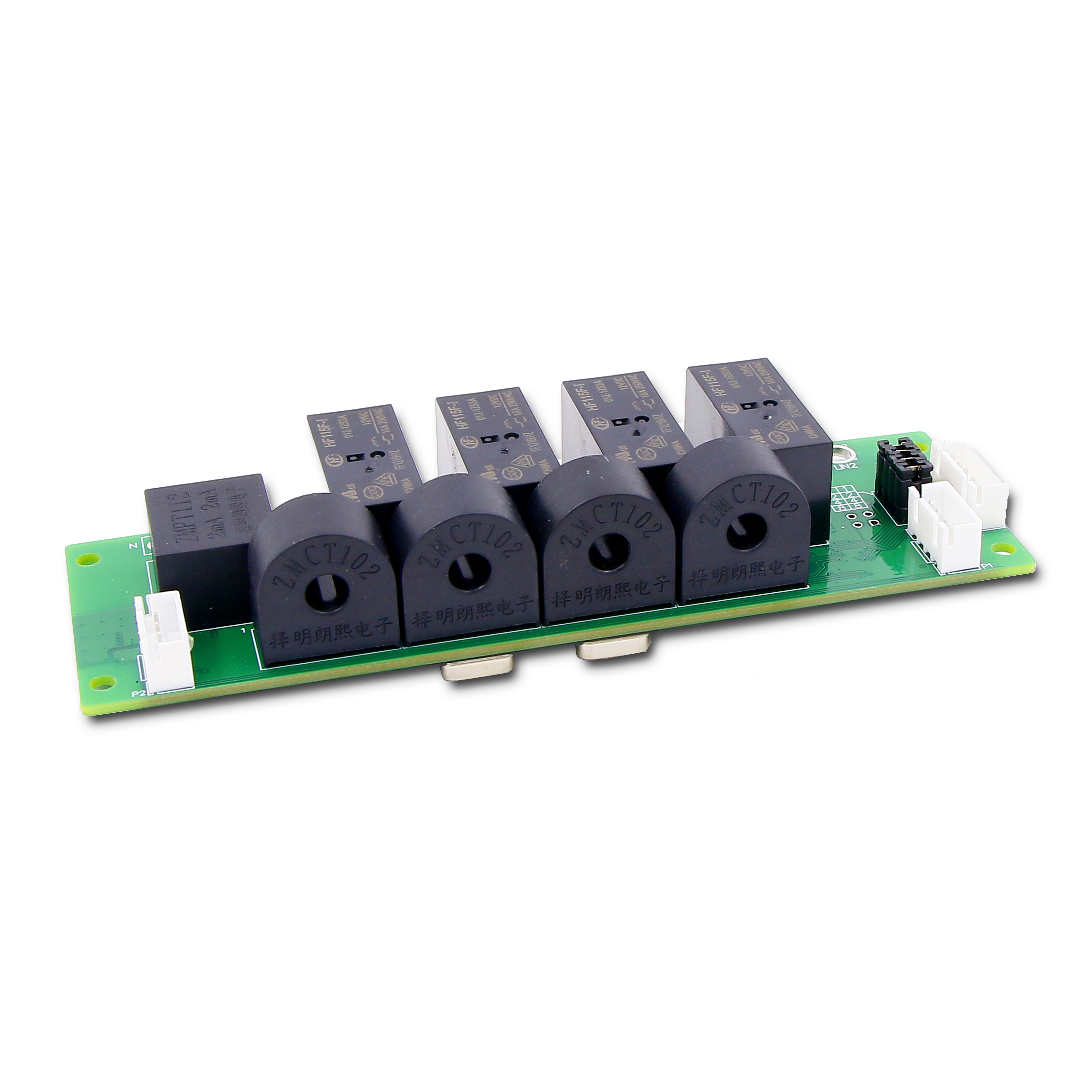
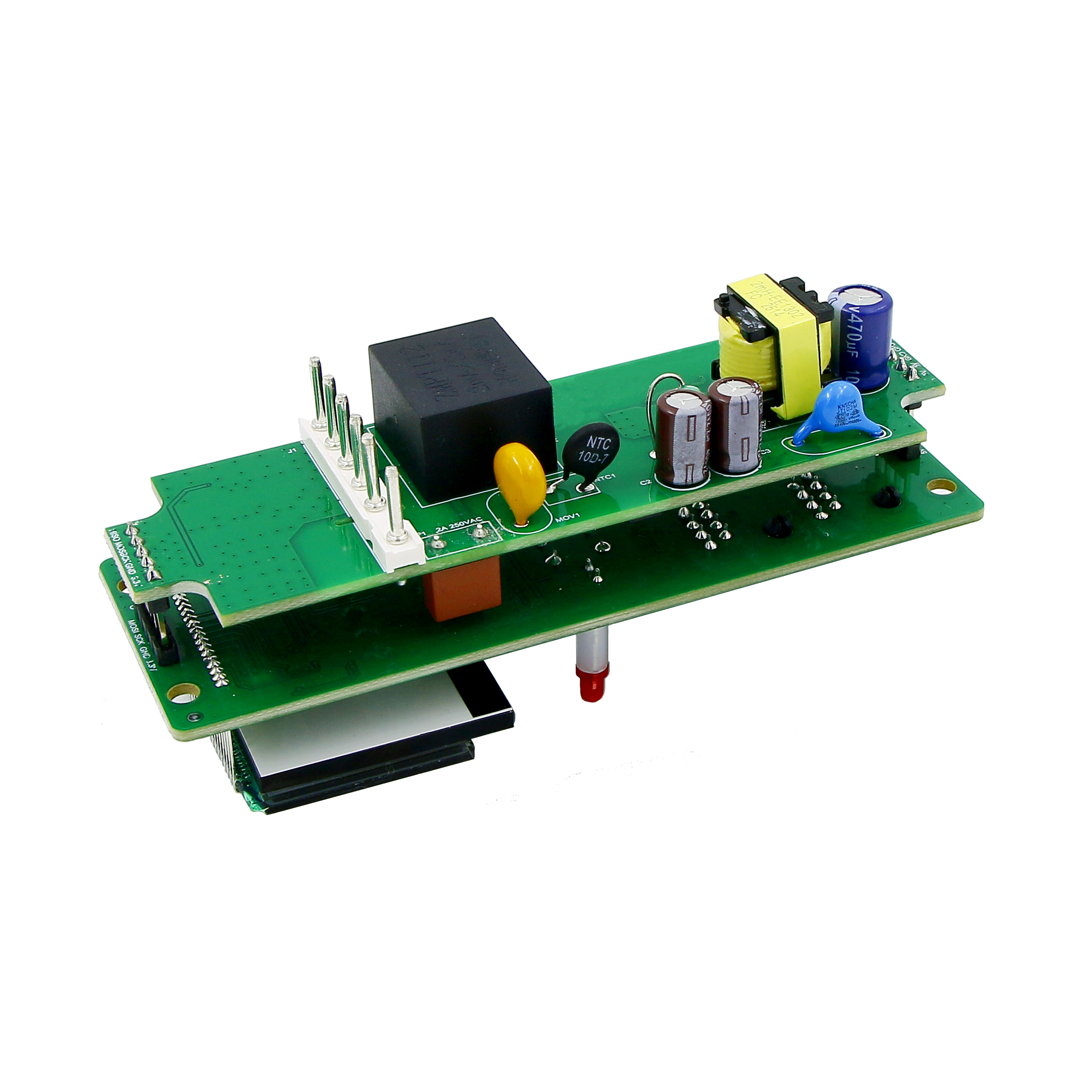
Power is checked first because it can be measured at the PDU itself, without sending anyone to the rack. On BOMPDU's Intelligent 2nd generation PDU the input side collects current, voltage, electrical energy and power — active, reactive, apparent and power factor — at a rated input of AC 110–250 V, 50/60 Hz, with a maximum load current range of 0–63 A. The output side collects the same parameter set per channel, and the output function is built as separate monitoring and control: each auxiliary module carries four outputs, and the main module supports up to eight auxiliary modules. Rated output current is a maximum of 16 A per single channel and 32 A per single board.
The most useful check at this stage is a comparison between the alarmed branch and its own commissioning baseline, not between that branch and a neighbour. Racks are rarely symmetrical; a branch carrying storage will legitimately draw more than a branch carrying network gear. This is the practical reason socket-level monitoring changes an incident: it bounds the anomaly to a channel instead of a rack.
Read the accuracy statement before reading the delta
Accuracy figures decide whether a difference is evidence or noise. On the Intelligent 2nd generation PDU, input voltage accuracy is stated as 0.5% across 85–250 V. Input current accuracy is stated as level 1 for 0.65–3.1 A and level 0.5 for 3.1–63 A. Output voltage accuracy is 1%, and output current accuracy is 2% over the 0.2–0.8 A monitoring range and 1% over 0.8–16 A.
The rule that follows: a change smaller than the stated accuracy band for that parameter cannot, on its own, be treated as proof that the load changed. A 5% rise on a heavily loaded branch sits outside the 1% band and deserves attention; a few percent on a light channel inside the 0.2–0.8 A range is closer to measurement uncertainty than to a fault. The alarm is not necessarily wrong — it needs a second, independent observation before it becomes a diagnosis.
What the power side can and cannot tell you
Per-outlet measurements answer which device or branch is behaving differently from baseline. They do not answer why. A current rise is consistent with a new workload, a failing power supply, a fan drawing more current, or a device that rebooted into a higher-power state, and the PDU cannot distinguish among them. What it can do is bound the problem to a branch, which is what makes the environmental check next so much faster.
Step 3 — Check the RS485 PDU layer, especially its configured thresholds
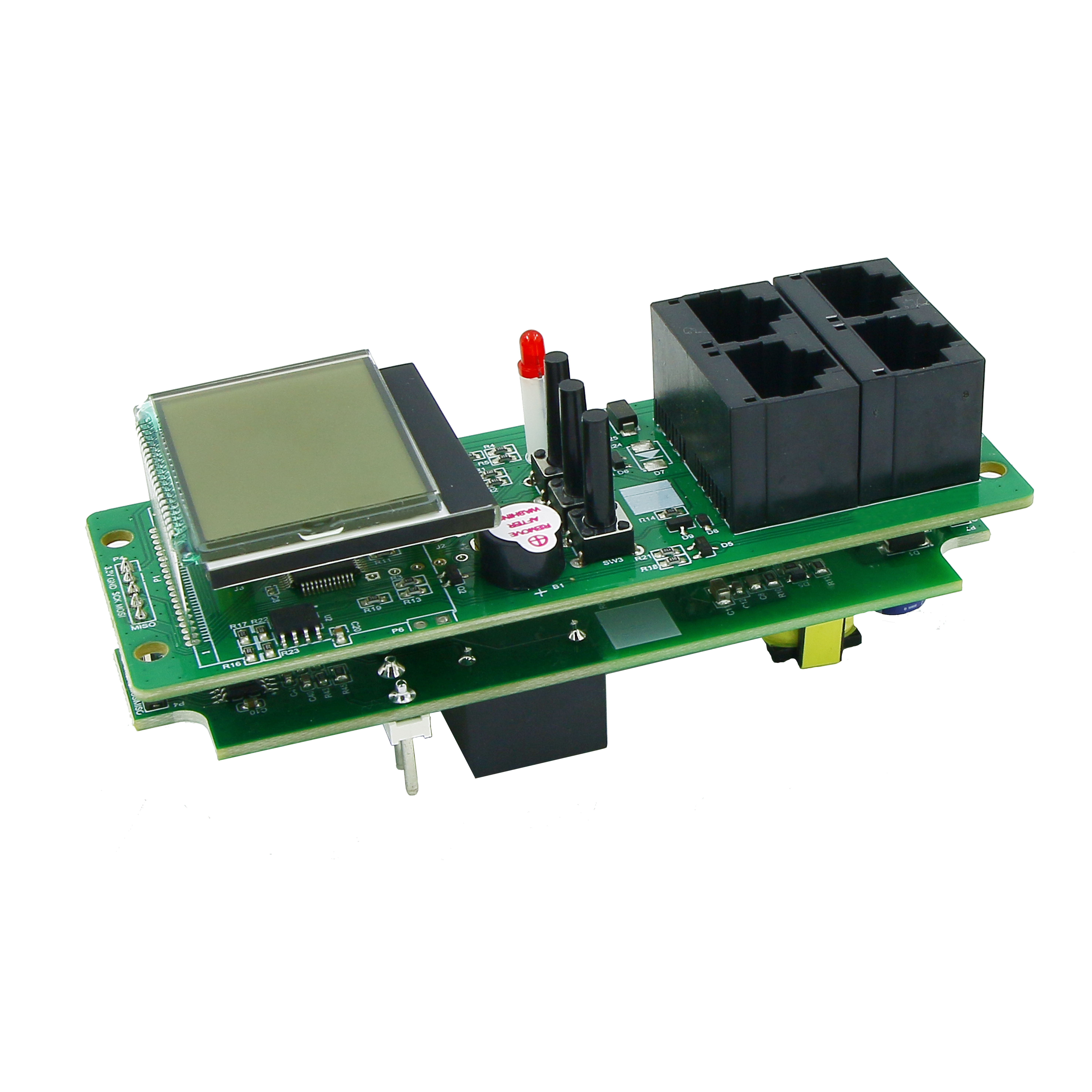
Where the rack uses a 1U/1.5U RS485 PDU instead of, or alongside, a Smart PDU, the same power check runs through Modbus. That unit has a rated input of 100–240 V with a working input range of 90–264 V, measures voltage across 90–264 V, and takes current through an external transformer. Voltage, current, power and energy are specified at Level 1 accuracy (1% ± 0.1), displayed to 0.01 V, 0.01 A, 0.01 kW and 0.01 kWh on a segment-code LCD. Communication is RS485 with the Modbus protocol. The caution function covers overvoltage, undervoltage and overcurrent alarms — and the parameters can be set.
That last detail resolves a large share of ambiguous alarms. A settable threshold is a configuration, and configuration drifts. When a rack is re-populated, or a PDU is moved between racks, the custom alarm threshold may still be the one chosen for the previous load. The triage question is therefore not only what the current is, but which limit this alarm was measured against, and who set it. Comparing the live reading with the commissioning record answers both.
Where a row mixes both product types, keep their roles clear. The RS485 PDU is a monitoring and alarming device with a Modbus output. The Smart PDU adds separate per-channel monitoring and control, which is what allows a remote switching action to be part of the response rather than only the record.
Step 4 — Isolate the environment side with the right sensor interface
Environmental faults are confirmed or excluded by the devices that detect them, and those devices do not share a single interface. Reading a sensor's interface before reading its value prevents a whole class of misdiagnosis, because a missing reading and a normal reading can look identical on a dashboard.
| Sensor | Model | Documented interface and key parameters | What it proves | What it does not prove |
|---|---|---|---|---|
| Temperature & humidity | BM-CGQ04 | I²C digital sensor; 2.2–5.5 V DC; 0–100 %RH at ±3 %RH typical (25 °C, 3.3 V); −40 to 80 °C at ±0.5 °C typical; factory calibrated; ESD ±4 kV (HBM, JEDEC JESD22-A114) | Air temperature and humidity at the sensing point, within stated conditions | The cause of the change, or conditions at another height in the rack |
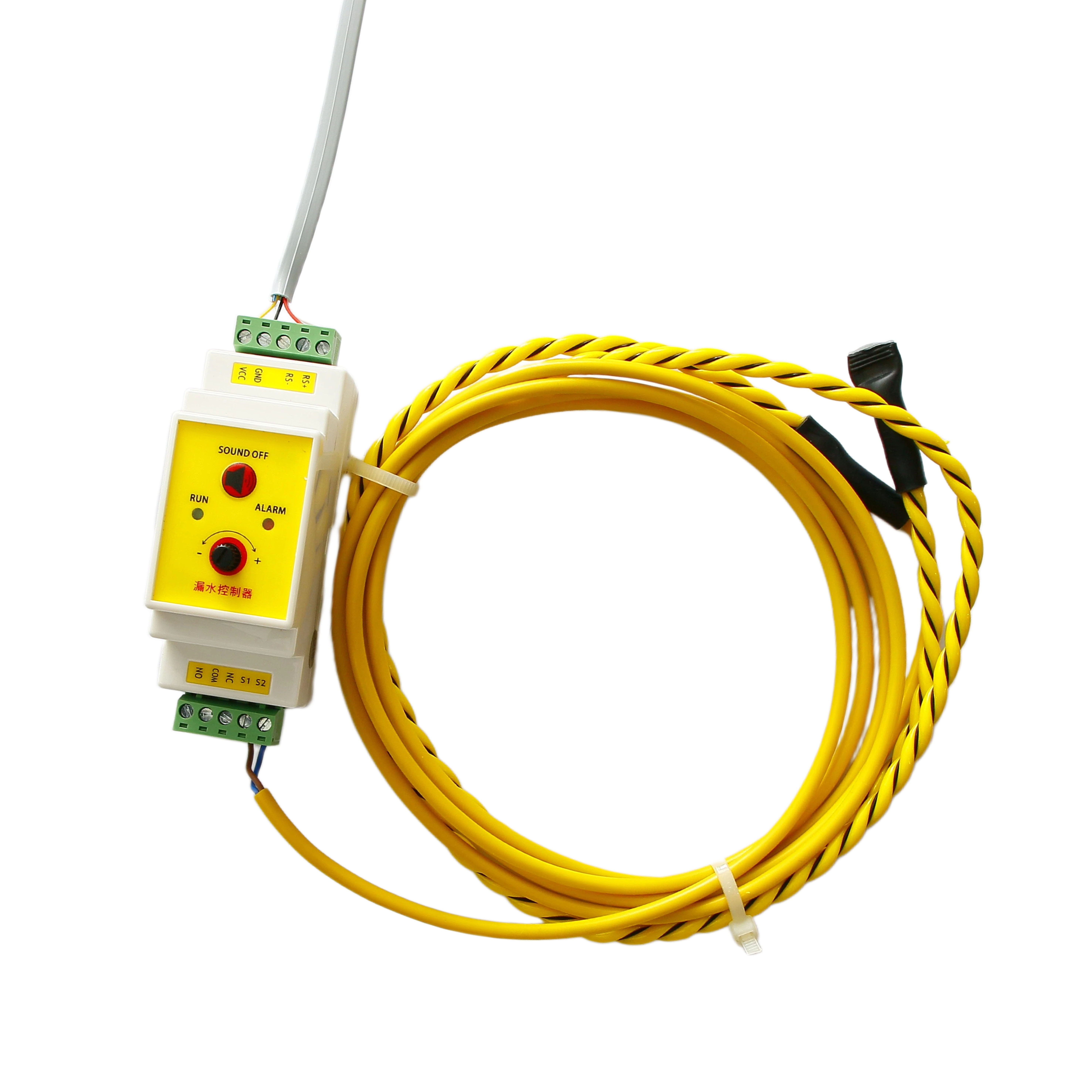
| Water leak | BM-CGQ06 | Leak detection controller; 12 V DC, 3 W; RS-485 / Modbus; SPDT relay output (NO/NC optional); sensing cable up to 500 m; RS-485 up to 1200 m without repeater; 35 mm DIN rail; power and communication LEDs | That the sensing cable is wet somewhere along its length, plus a relay state for interlock | The exact leak position without cable mapping, or anything about air temperature |
| Smoke | BM-CGQ05 | Wired photoelectric smoke detector; 10–35 V DC; alarm signal output; status LED; 2-wire or 4-wire configuration; wall or ceiling mount on a standard base | That the detector asserted its alarm output | Smoke density trends, or the source of combustion |
| Door position | BM-CGQ07 | Dry contact sensor; NO/NC configurable; 5–30 V DC; 100 mA max switching; <100 mΩ closed, >100 MΩ open; actuation gap ≤15 mm; −10 to +55 °C; IP40; 1 m cable standard | Open or closed state of the monitored door or panel | Why it opened, or whether airflow actually changed |
The temperature and humidity path deserves a note on how to read its accuracy line. BM-CGQ04's ±3 %RH and ±0.5 °C figures are stated as typical at 25 °C and 3.3 V. That is a specification at a condition, not a promise across the whole −40 to 80 °C range, so a reading taken in a hot rack is directionally reliable rather than calibration-grade. The sensing element is factory calibrated, and its ESD rating is stated to JEDEC JESD22-A114 at ±4 kV HBM — relevant when a sensor sits on a board inside a cabinet that technicians open and touch.
For leak detection, the BM-CGQ06 controller's two LEDs do a specific job: one shows power, the other shows communication. If the communication LED is not indicating, the correct conclusion is that the water state is unknown, not that there is no leak — and the response changes from inspecting the floor to inspecting the RS-485 segment. Its 500 m maximum sensing cable length and 1200 m RS-485 range without a repeater are the numbers to check when a room was extended after the original installation.

The door sensor is often the cheapest way to explain a temperature alarm. If the rack door or a containment panel opened shortly before the temperature rose, the temperature change has a plausible physical cause that requires no component replacement — a conditional explanation to verify against the access log, not an automatic conclusion. BM-CGQ07's ≤15 mm actuation gap and screw or surface mounting matter here: a sensor mounted too far from its magnet reports a door as open when it is closed, and the resulting alarm pattern is indistinguishable from a real access event until someone measures the gap.
The smoke detector plays a different role from the other three. BM-CGQ05 provides a discrete alarm output rather than a trend, and air temperature, humidity, leak state and door position are irrelevant once it asserts. A smoke alarm is a safety escalation: site procedure takes precedence, and no amount of remote diagnosis belongs in front of evacuation.
Step 5 — Read the combination, not the single alarm
Once power readings and sensor states are both in hand, the alarm pair usually resolves into a recognisable signature. The table below is a decision aid, not a diagnostic standard; site procedures and manufacturer documentation always take precedence, particularly for smoke and leak events.
| Observed signature | First domain | Next check | What would change the conclusion |
|---|---|---|---|
| Branch current above baseline and top-of-rack temperature rising within minutes | Power, with environment secondary | Per-channel current against commissioning baseline; is the delta outside the stated accuracy band? | A device was added or moved, which makes the temperature rise a consequence and the fix a matter of capacity or airflow |
| Temperature rising while current stays flat | Environment | Door or panel contact state, then airflow; confirm the sensor is communicating | The door contact opened at the same time, which points to an airflow event |
| Humidity climbing with no leak relay | Environment | Whether the reading sits inside the sensor's stated operating conditions; compare a second point | A single humidity reading turning out to be a stale value |
| Leak controller relay active | Safety and environment | Locate the sensing cable run, isolate the affected area | Nothing on the power side changes this priority |
| Smoke detector alarm output active | Safety | Follow site fire procedure immediately | No remote diagnostic step precedes escalation |
| PDU reports an outlet off while the device is unreachable | Power | Verify per-channel output current and the control state as two separate records | The branch alarm and the outlet state turn out to be one event, not two |
| Environmental values unchanged for hours while other sensors move | Communication | RS-485 segment, controller LEDs, monitoring link | The values turn out to be current, which returns the case to Step 4 |
Step 6 — Confirm remotely, then close out with evidence
The reason to invest in a remote control PDU is that part of this sequence can be completed without a site visit. BOMPDU reports two documented applications that show the boundary. In an airport data center installation of 800 units, the platform was used to monitor current, voltage, energy and power for each socket, with three years of stable operation reported. At a data center server manufacturer, 2000 units were used in a server aging test with remote on/off control and real-time monitoring, supporting unmanned on-site operation over a two-year period.
What those applications demonstrate is monitoring and remote switching as an operating model. They do not demonstrate that remote switching is the right answer for every alarm. The rule that follows is narrower: remote action is appropriate when the power measurements identify a specific branch, the environmental readings are current rather than stale, and the action does not conflict with a safety event. When any of those conditions is missing, the correct output of triage is a dispatch with a described symptom, not a remote command.
Close the loop by recording four things: the alarm category from Step 1, the measured values with units and the accuracy band that applies, the sensor states at the same timestamp, and the action taken. That record is what turns the next occurrence from a repeat investigation into a comparison.
Where the same triage path applies
The sequence does not change with the building, but the emphasis does.
- Data center and cloud (IDC construction). Stable server power, remote power control and energy consumption monitoring, with servers, switches, UPS and environmental monitoring units as supporting equipment. The data center PDU is the primary evidence source; sensors confirm or exclude the environmental explanation.
- Telecommunications. Outdoor base station power with BBU, RRU and battery pack, where remote reboot and voltage and current monitoring are core functions. Wide temperature range and lightning protection are specification priorities, and a temperature outside the equipment's rated range is itself a finding.
- Government and command centers. Emergency command conditions with server, KVM and large display loads. Dual power input, high reliability and alarm notification are the stated requirements, so alarm routing matters as much as alarm detection.
- Industrial automation. Automated production lines using RS485 control and status collection alongside PLC, touch screen and sensors, where Modbus-RTU and interference resistance dominate. For an industrial smart PDU in this setting, a serial monitoring layer is often the whole requirement.
- Transportation. Road traffic monitoring in intelligent traffic systems, running continuously with cameras, optical transceivers and industrial PCs, where surge protection and rail mounting are part of the installation.
What the ISO 9001:2015 certificate tells a buyer — and what it does not
BOMPDU holds ISO 9001:2015 certification for PDU control-board design and development, issued by NOA Testing & Certification Group Ltd. under certificate 05126Q03324R001. Read the scope carefully, because it explains why the certificate is relevant to exactly the problem this article describes. The control board is the part of a Smart PDU that determines what is measured, how thresholds are applied, and what is reported upstream. A management-system certificate covering that design and development activity is evidence that the process behind those decisions is defined and audited. It is the right document to request when you intend to rely on a PDU's measurement and alarm logic during an incident.
It is not a product safety certification, and treating it as one is a common procurement shortcut. IEC 62368-1:2023 is the safety standard for ICT and AV equipment, including PDUs, in most major jurisdictions, according to the IECEE. Both questions belong in a supplier file and are answered by different documents: the ISO 9001 certificate addresses process and design control, while safety compliance is a product-level question with its own test evidence.
| Evidence | What it covers | Question it answers |
|---|---|---|
| ISO 9001:2015 — NOA Testing & Certification Group Ltd., certificate 05126Q03324R001 | Quality management system for PDU control-board design and development | Is the design and development process defined and audited? |
| IEC 62368-1:2023 — product safety standard cited by IECEE / IEC | Safety requirements for ICT and AV equipment | Does the product meet the applicable safety standard? |
| Stated production practice: 100% test, with in-house burn-in and high–low temperature test equipment | Production and screening activity | Is each unit tested before shipment, and with what equipment? |
For context on the manufacturer behind these products: BOMPDU (Wuxi Bom Electronic Technology Co., Ltd.) was established in 2018 in Wuxi, Jiangsu Province, and builds both product families referenced here — the Intelligent 2nd generation PDU and the 1U/1.5U RS485 PDU — with OEM/ODM customization available for metering and control, outlet number, and single- or three-phase input.
Specify for the alarm you have not had yet
Most of this triage is decided at procurement, months before any alarm. A specification that supports it includes the following.
- Measurement points, explicitly. Branch-level only, or per-outlet current and power. The difference determines whether Step 2 can bound a fault to one device.
- Whether alarm thresholds are settable, and who records them. If they are, the commissioning record becomes a triage document. The RS485 PDU's overvoltage, undervoltage and overcurrent parameters can be set; ask for the configured values in writing.
- Sensor interface per model. RS-485/Modbus on the leak controller, dry contact on door position, a discrete alarm output on smoke, and a digital interface on the temperature and humidity element. Mixing these assumptions up in a bill of materials is a common source of a sensor that appears not to report.
- Physical limits. 500 m maximum sensing cable and 1200 m RS-485 range without a repeater on the leak controller; 35 mm DIN rail space; a ≤15 mm actuation gap on the door sensor.
- Remote control scope. Which outlets can be switched remotely, and whether site procedure permits that action.
- Feature questions to confirm at model level. If the row requires IPv6-only management, master-slave cascading, sequential power-on or phase switching, request the exact model's documentation rather than assuming a category-wide capability.
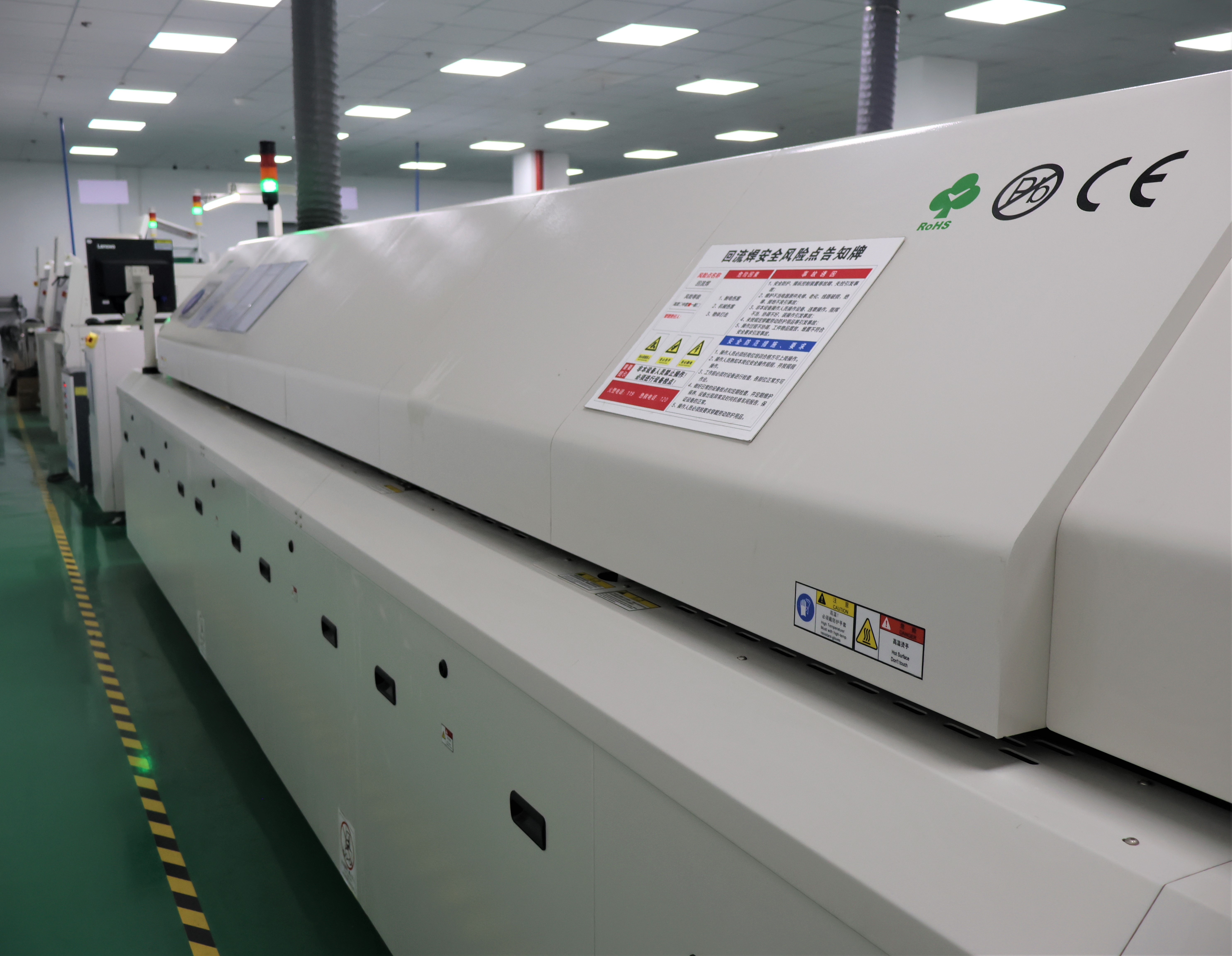
- Supply terms. BOMPDU's stated production parameters are a 30-day lead time, 100% test, OEM/ODM customization, and remote after-sales support.
Next step: if you are specifying rack power for a site where alarms will be triaged remotely, the specification sheets are the fastest way to confirm measurement points, alarm configuration and sensor interfaces. Download the BOMPDU product brochure (PDF).
FAQ
Does the ISO 9001:2015 certificate cover the PDU product itself?
No. The certificate held by BOMPDU covers the quality management system for PDU control-board design and development, issued by NOA Testing & Certification Group Ltd. under certificate 05126Q03324R001. It is evidence about the design and development process, not a product safety certification. Product safety is a separate question, answered against the applicable standard — IEC 62368-1:2023 for ICT and AV equipment in most major jurisdictions — with its own test evidence. Buyers should request both, because they answer different questions and neither substitutes for the other.
Can a Smart PDU distinguish an overload from a cooling failure?
Not by itself. A Smart PDU measures electrical parameters — on the Intelligent 2nd generation PDU these are current, voltage, electrical energy and active, reactive and apparent power plus power factor, at input and per output channel, with stated accuracies such as 0.5% for input voltage and 1% for output current over 0.8–16 A. It can show that one branch changed relative to its own baseline. Distinguishing an overload from a cooling failure requires the environmental side: a temperature and humidity reading, a door or panel state, a leak controller relay, and a smoke detector output. The domain split, not a single device, produces the answer.
Why would a rack alarm turn out to be a configuration problem?
Because alarm thresholds can be set and settings persist after the load changes. The 1U/1.5U RS485 PDU includes overvoltage, undervoltage and overcurrent alarms with parameters that can be set. When a rack is re-populated or a PDU is moved, the limit may still reflect the previous configuration, so a legitimate load looks like a fault. Comparing the live reading with the commissioning record — and with the stated Level 1 accuracy of 1% ± 0.1 on that unit — separates a real excursion from a stale limit.
What should a buyer request before relying on remote triage?
Three things. First, a sample or evaluation unit configured with the measurement points you intend to use, so per-outlet or per-branch visibility is confirmed rather than assumed. Second, the alarm configuration as shipped, in writing, including which parameters are settable. Third, interface documentation for every sensor model in the bill of materials — RS-485/Modbus on the BM-CGQ06 leak controller, dry contact on the BM-CGQ07 door sensor, a discrete alarm output on the BM-CGQ05 smoke detector, and a digital interface on the BM-CGQ04 temperature and humidity element. OEM/ODM customization for metering and control is available, so confirm which items are standard and which are configured.
How long does supply take for a configured unit?
BOMPDU states a 30-day lead time, with OEM/ODM customization covering metering and control, outlet number, and single- or three-phase input, and 100% test before shipment. For a first order, allow evaluation time before that lead time — the sample stage is where measurement points and sensor interfaces should be settled. To discuss a configuration, sample or quotation, contact the BOMPDU team through the product brochure or the company website.
Conclusion
An alarm on a rack is a claim about one domain. The sequence above tests that claim in the cheapest order available: classify what generated the alarm, read the PDU's own measurements against their stated accuracy and the rack's commissioning baseline, check whether the alarm limit is still the right one, and only then interpret the environmental sensors — whose interfaces decide whether a missing reading means normal or unknown. When the power and environment evidence agree, the response is obvious. When they disagree, the disagreement is itself the finding, and it is worth more than either alarm alone.
The products in this path are ordinary rather than exotic: a Smart PDU that measures input and output separately and can switch remotely, an RS485 PDU that reports over Modbus with settable alarm limits, and four sensor types whose documented interfaces make the environmental side legible. Specified with their limits in view — 500 m of leak sensing cable, a 1200 m RS-485 run, a 15 mm door actuation gap, stated accuracies at stated conditions — they turn an overnight alarm into a decision instead of a dispatch.