22
11/2026
Solving Power and Environmental Silos with a Smart PDU
Learn how to break power and environmental monitoring silos by verifying a Smart PDU power foundation, then adding leak, smoke, door, and temperature/humidity sensors.
Solving Power and Environmental Monitoring Silos with a Smart Power Distribution Unit
A data center team can install a Smart Power Distribution Unit for outlet-level power visibility and still manage leak, smoke, door, and temperature/humidity risk in a separate system. The rack then has two monitoring views: one for electrical load and one for the room environment. Closing that gap is not a matter of buying more sensors. It requires a staged architecture: define the power and control foundation, verify the control-board design evidence behind that foundation, then add environmental coverage with interfaces and alarm logic that can be operated together.
Why Power and Environmental Monitoring Drift Apart
Power and environmental monitoring usually become separate because they are specified by different teams. The power team selects a PDU for input and outlet monitoring, remote control, and electrical alarms. The facilities or safety team selects water leak, smoke, door, and temperature/humidity devices for the room. Each purchase can be correct on its own. The silo appears when the two sets of alarms arrive in different consoles and no one owns the correlation.
According to a 2024 ResearchAndMarkets industry report cited in the verified data for this topic, intelligent PDUs accounted for more than half of total PDU market revenue as of 2023. That supports a practical assumption: many new rack power designs will include a smart power layer. It does not mean the environmental layer is integrated. The environmental devices in this guide use several interfaces: the BM-CGQ06 water leak detector uses RS-485 Modbus, the BM-CGQ07 door sensor uses a dry contact, the BM-CGQ05 smoke detector provides an alarm signal output, and the BM-CGQ02 and BM-CGQ04 temperature/humidity sensors use I²C. Different interfaces are manageable when they are mapped in advance. They become a silo when each device is left to its own controller and dashboard.
A Staged Architecture: Power Foundation First
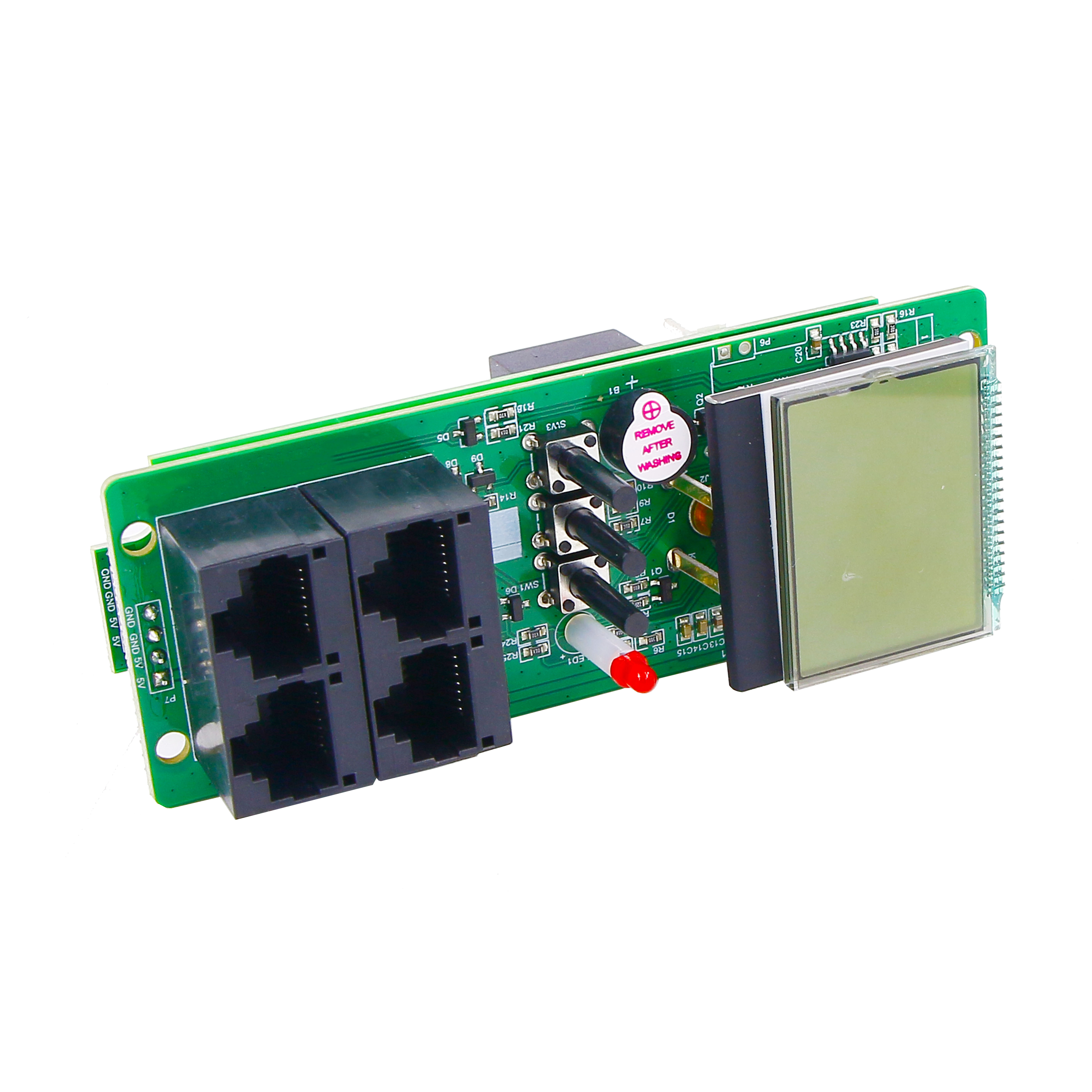
The first stage is the power and control foundation. For a data center rack, that foundation has two jobs: show what the load is doing and provide a controlled way to act on it. The BOMPDU Intelligent 2nd generation PDU product from Wuxi Bom Electronic Technology Co., Ltd. (BOMPDU), a Wuxi, Jiangsu-based manufacturer of end-of-row power distribution solutions for data centers established in 2018, is specified for AC110V-250V 50/60Hz input, single-phase or three-phase input, and a maximum load current of 0-63A. It collects input current, voltage, energy, and power, including active power, reactive power, apparent power, and power factor. Its output side collects current, voltage, energy, and power, and provides separate monitoring and control. Rated output current is a maximum of 16A per channel and 32A per board.
The 1U_1.5U 485 PDU adds a different control link. Its specification lists an RS485 interface using the Modbus communication protocol, a 100V-240V rated input voltage, a 90V-264V input voltage range, and settable overvoltage, undervoltage, and overcurrent alarms. The current measurement uses an external transformer. Voltage, current, power, and electricity measurements are stated with Level 1 accuracy of 1% ± 0.1 within the rated input voltage range for voltage, and the display resolution is 0.01V, 0.01A, 0.01kW, and 0.01kWh. In a staged architecture, the Smart PDU provides the outlet-level monitoring and control layer, while the RS485 PDU provides a serial Modbus link for power data and alarm parameters.

Before placing a purchase order, turn the product family names into model-level requirements. Secondary keywords such as Remote Control PDU, Socket-Level Monitoring PDU, Sequential Power-On PDU, Single/Three Phase Switchable PDU, Custom Alarm Threshold PDU, Cascadable Master-Slave PDU, Network Managed PDU, Data Center PDU, and Industrial Smart PDU describe different procurement concerns, not a single feature bundle. For example, the supplied Smart PDU specification states single-phase and three-phase input options. It does not state automatic phase switching. If your RFQ uses the term single/three-phase switchable PDU, ask for the exact model's documented switching behavior. The RS485 PDU specification does state settable overvoltage, undervoltage, and overcurrent alarms, which supports a custom alarm threshold requirement at the model level. If sequential power-on, master-slave cascading, IPv6, or a specific network-management protocol is required, add it as a separate line item and ask for model-level evidence. Do not infer those capabilities from a product name.
The same discipline applies to load planning. The Smart PDU maximum load current is 0-63A, but the output side has a single-channel maximum of 16A and a single-board maximum of 32A. A rack full of high-density servers can exceed a per-channel limit even when the input rating looks adequate. The power foundation should therefore record the input phase, breaker and connector details, outlet count, per-channel load, and the monitoring granularity required. That record becomes the reference for the environmental stage.
The Verification Gate: Control-Board Evidence Before Sensor Expansion
Before adding environmental sensors, verify the design evidence behind the power layer. The BOMPDU ISO 9001:2015 certificate 05126Q03324R001, issued by NOA Testing & Certification Group Ltd., covers PDU control-board design and development. That is a quality management system certification scoped to the design and development of PDU control boards. It is evidence about the management system for that scope; it is not a product performance rating and it does not by itself guarantee field results. Read it as a verification checkpoint, not as a substitute for electrical testing or site acceptance.
The control board matters because it carries the monitoring and control functions that make a PDU smart. If the power layer is built on an undocumented control design, the environmental layer inherits that uncertainty: alarms may be difficult to trace, change control may be unclear, and production consistency may be harder to audit. The certificate gives the buyer a concrete item to check: certificate number, issuer, standard, and scope language. Keep the scope wording with the claim. A general statement that a company is ISO 9001 certified is weaker than a statement that the relevant certificate covers PDU control-board design and development.
This verification gate also improves the sensor plan. Once the power layer's control-board scope is documented, the team can ask the same supplier for consistent change control, production test records, and model-level specifications. It can then decide which environmental devices need their own controllers and which can be brought into a common monitoring layer. The sequence matters: verify the power foundation, then expand the monitoring perimeter.
Sensor Coverage Map for a Rack Environment
Environmental monitoring should be organized by failure mode. A rack environment plan typically needs water, smoke, access, and heat/humidity coverage. The devices below are not interchangeable; each has a specific interface and installation requirement. The goal is not to add every sensor to every cabinet. The goal is to place the right sensor where its failure mode can occur and to route its signal to the monitoring layer that will act on it.
Water leak: BM-CGQ06
The BM-CGQ06 water leak detector is a leak detection controller with a 12V DC, 3W supply, an SPDT relay output that can be normally open or normally closed, and an RS-485 communication interface using the Modbus protocol. Its maximum sensor cable length is 500 m, and its RS-485 communication range is up to 1200 m without a repeater. It is designed for 35 mm DIN-rail installation and operates from -25°C to 50°C at 5%-90% RH non-condensing. The RS-485 Modbus link is the key integration point: it allows leak status to be read by a Modbus-capable monitoring layer rather than remaining inside a standalone leak panel.
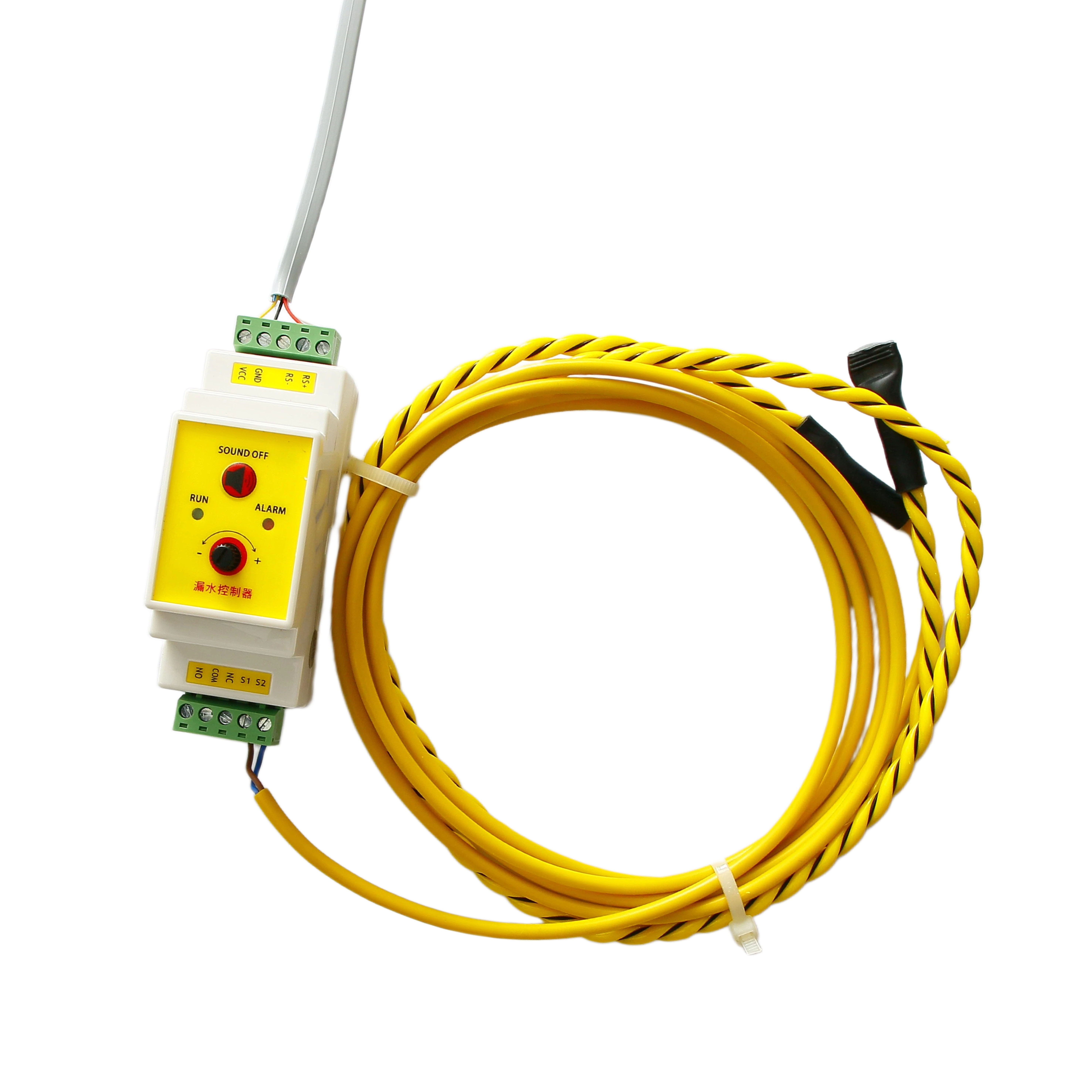
Placement should follow the water path, not the rack outline. Common risk points include under raised floors, near cooling units, along pipe runs, at roof penetrations, and at the base of cabinets where condensation or spill can collect. The leak detector's 500 m sensor cable capacity and 1200 m RS-485 range make it suitable for a distributed sensing layout, but the cable route and Modbus addressing should be planned before installation.
Smoke: BM-CGQ05
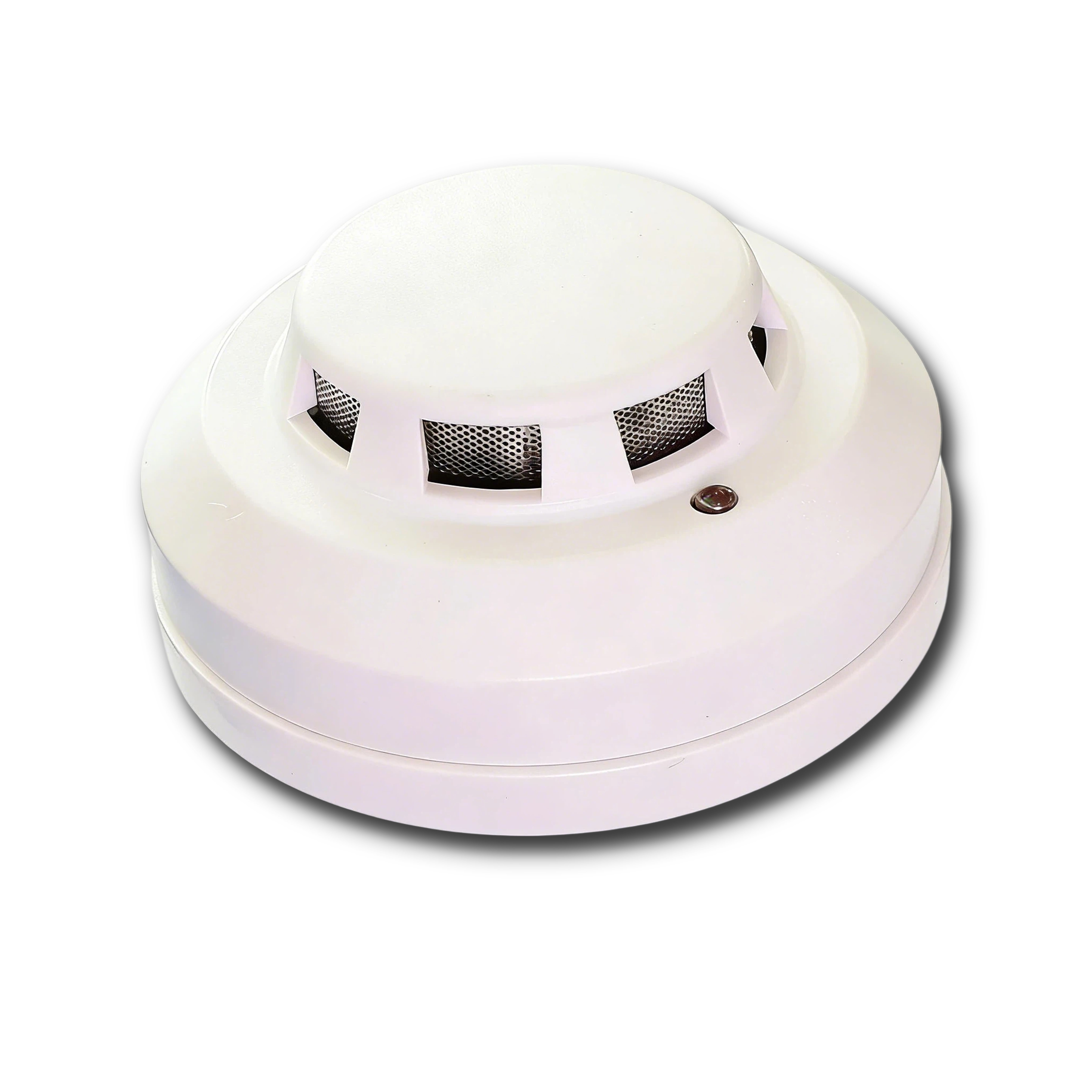
The BM-CGQ05 is a wired smoke detector with a 10-35V DC power supply, photoelectric or optical smoke sensing, an LED alarm indicator, and an alarm signal output. It supports wall or ceiling mounting on a standard base and 2-wire or 4-wire configuration. Its listed certification is an industrial-grade application standard. In a rack monitoring plan, the smoke detector is a fire-risk input, not a power-quality sensor. Its alarm output should be mapped to the monitoring layer as a separate alarm class so that it is not buried among routine power events.
Door: BM-CGQ07
The BM-CGQ07 door sensor uses a dry contact that can be configured as normally open or normally closed. It operates from 5-30V DC, has a maximum switching current of 100 mA, a contact resistance below 100 mΩ in the closed state, and insulation resistance above 100 MΩ in the open state. The actuation gap is ≤15 mm, the protection rating is IP40, and the standard cable length is 1 m with customization available. Because it is a dry-contact device, it needs a digital input or a dry-contact interface on the monitoring layer. It does not produce a Modbus message on its own.

Temperature and humidity: BM-CGQ02 and BM-CGQ04
BOMPDU lists two digital temperature and humidity sensors. The BM-CGQ02 uses an I²C interface, a 2.2-5.5V DC supply, and provides ±2% RH typical humidity accuracy and ±0.3°C typical temperature accuracy. The BM-CGQ04 also uses I²C, with ±3% RH typical humidity accuracy and ±0.5°C typical temperature accuracy at 25°C and 3.3V. Both are factory-calibrated digital sensors in SMD packages. The choice between them should follow the accuracy requirement and the controller interface, not the product name alone.

The important integration point is that these are I²C sensors. They are not RS-485 devices. A monitoring layer that accepts RS-485 Modbus will still need an I²C gateway or controller for the temperature/humidity sensors. That requirement should be visible in the bill of materials. If it is omitted, the temperature and humidity data will remain in a separate silo even though the leak detector is on the main Modbus bus.
Integration Rules for Mixed Interfaces
A realistic rack monitoring layer should be specified by interface type. The power layer may use the RS485 PDU's Modbus link and the Smart PDU's outlet-level monitoring and control. The environmental layer adds RS-485 Modbus for the leak detector, dry contact for the door sensor, an alarm output for the smoke detector, and I²C for the temperature/humidity sensors. The integration question is not whether one product can do everything. The question is which device owns each interface and how the data reaches a common alarm workflow.
- Inventory every interface before wiring. List the RS-485 Modbus devices, dry-contact inputs, alarm outputs, and I²C sensors separately. Record the protocol, address, cable type, and power requirement for each device.
- Assign Modbus addresses and register maps. The leak detector and the RS485 PDU both use Modbus, but they are different device types with different register maps. Confirm the polling plan, baud rate, parity, and address range with the monitoring layer supplier.
- Treat dry contacts as digital inputs. The door sensor's NO/NC dry contact needs a digital input card or a dry-contact interface. Confirm whether the monitoring layer can invert the state and label the open/closed condition correctly.
- Separate alarm outputs from data buses. The smoke detector's alarm signal output should be wired as a dedicated alarm input, not merged into a data bus without a clear alarm class. This keeps fire-risk events distinct from power-threshold events.
- Plan the I²C gateway. The BM-CGQ02 and BM-CGQ04 are I²C sensors. Place the gateway or controller according to the sensor's bus requirements and confirm that the monitoring layer can read the calibrated values.
- Test the response path, not only the reading. A sensor that reports a value but cannot trigger the intended notification is not integrated. Test each alarm class, the notification route, and the escalation owner before the rack goes live.
The supplied PDU specifications describe power monitoring and RS485/Modbus communication; they do not list environmental sensor input ports. That is not a defect in the power layer. It is a boundary condition for the architecture. Environmental sensor inputs should be treated as a separate integration requirement, satisfied by a monitoring controller, gateway, or building management interface that accepts the actual sensor outputs.
Alarm Design and Fault Correlation
Alarm design is where the silo either closes or reappears. A unified monitoring layer should present power and environmental events with the same rack identifier, timestamp, source, and severity model. The RS485 PDU's overvoltage, undervoltage, and overcurrent alarms can be set as parameters. The environmental layer should define separate thresholds for leak, smoke, door, and temperature/humidity. The point of correlation is not to merge every alert into one severity. The point is to let an operator see related events in one timeline.
Consider a conditional example. If a water leak alarm and a humidity rise occur in the same rack zone within a short interval, an operator who sees both events together can investigate the water source before the humidity affects the load. If the two events sit in separate consoles, the correlation depends on manual review. The same logic applies to a door-open event followed by an unexpected power change: the access event may explain the power event, or it may be unrelated. A common timeline makes that question visible without asserting a cause that the data has not established.
Use alarm classes that match the response. Smoke should be a fire-risk class with an immediate escalation path. Water leak should be a facility-risk class with a defined response. Door access should be a security or maintenance class, not a fire alarm. Power threshold alarms should distinguish input-side and outlet-side conditions. The monitoring layer should record which sensor or PDU produced the alarm and whether the condition is still active. That record is more useful than a single summary light on the rack.
Where This Fits: Data Center and Industrial Rack Scenarios
The primary fit is the data center rack. The BOMPDU application data for data centers describes stable server power supply, remote power control, and energy consumption monitoring, with servers, switches, UPS, and environment monitoring units as supporting equipment. That description aligns with the staged architecture: the Smart PDU handles the power and control foundation, while the environment monitoring unit and sensor layer handle the room conditions. The two layers serve different risk questions and should be planned together.
Industrial and edge cabinets have a similar pattern but different constraints. The manufacturing application data describes automated production lines with power control via RS485 and status collection, matched with PLC, touch screen, and sensors, and requiring Modbus-RTU with strong anti-interference. In that setting, the RS485 PDU's Modbus link is a natural fit for the power layer, while environmental sensors should be selected for the cabinet's actual exposure. A factory floor may need door and temperature monitoring more than a raised-floor leak grid; a telecommunications outdoor site may prioritize remote reboot and voltage/current monitoring with wide temperature and lightning protection. The architecture is reusable, but the sensor map is site-specific.
Existing cases show the power-monitoring layer in use. An airport data center case lists 800 units used for monitoring electricity usage, with real-time monitoring of current, voltage, energy, and power for each socket, and a three-year stable result. A data center server manufacturer case lists 2,000 units used for server aging tests, with remote on/off control, real-time monitoring, and unmanned on-site operation, and a two-year stable result. These cases support the power-monitoring application. They do not by themselves prove environmental integration outcomes, which depend on the sensor selection, interface design, and site acceptance described in this guide.
Comparison: Three Monitoring Approaches
The table below compares three practical approaches at the architecture level. It is not a product ranking. The integrated approach depends on a monitoring layer that accepts the listed interfaces and on a site-specific sensor map.
| Dimension | Power-only with Smart PDU | Environment-only sensors | Planned power + environment integration |
|---|---|---|---|
| Primary visibility | Input and outlet current, voltage, energy, and power; active, reactive, apparent power, and power factor on the Smart PDU. | Leak, smoke, door, and temperature/humidity conditions at the sensor locations. | Electrical and environmental events in one monitoring workflow, with each source identified. |
| Control capability | Separate monitoring and control per output; RS485 PDU supports Modbus communication and settable overvoltage, undervoltage, and overcurrent alarms. | Detection and status output; the leak detector provides an SPDT relay and RS-485 Modbus, while the door sensor provides a dry contact. | Power control plus environmental alarms; response paths are defined by alarm class and escalation owner. |
| Typical interfaces | RS485/Modbus on the RS485 PDU; outlet-level monitoring and control on the Smart PDU. | RS-485 Modbus, dry contact, alarm output, and I²C, depending on the sensor. | All of the above, with a controller or monitoring layer that accepts each interface. |
| Alarm correlation | Power events are visible in the power console. | Environmental events are visible in the environmental console. | Events share rack ID, timestamp, source, and severity so related conditions can be reviewed together. |
| Fit condition | The rack already has stable power distribution and the main need is load visibility and remote control. | The main need is room safety and environmental condition monitoring, with power handled separately. | The team wants one operating view and can define interface ownership, alarm classes, and acceptance tests. |
| Main limitation | Environmental risk remains outside the power view unless a separate layer is added. | Power load and outlet-level control are not covered by environmental sensors. | Requires planned gateways and I/O; it is an architecture, not a single-box promise. |
The comparison makes the trade-off explicit. A power-only deployment can be technically sound and still leave environmental risk in a silo. An environment-only deployment can protect the room and still lack outlet-level power control. The integrated approach is the most demanding to specify because it has the most interfaces, but it is also the only approach that gives the operator one place to review both risk types. The decision should be based on the operating model, not on the number of devices.
Implementation Checklist
- Define the rack's power profile: input phase, maximum load current, per-channel load, outlet count, and required monitoring granularity.
- Select the power foundation: Smart PDU for outlet-level monitoring and control; RS485 PDU for RS485/Modbus power data and settable electrical alarms where required.
- Verify the control-board evidence: certificate 05126Q03324R001, issuer NOA Testing & Certification Group Ltd., standard ISO 9001:2015, and scope covering PDU control-board design and development.
- Map environmental failure modes to devices: water leak, smoke, door access, and temperature/humidity. Place each sensor where its failure mode can occur.
- Assign interfaces: RS-485 Modbus for the leak detector, dry contact for the door sensor, alarm output for the smoke detector, and I²C gateway for the temperature/humidity sensors.
- Configure alarm classes and test the response path: power threshold, fire risk, water risk, access, and environmental condition. Confirm notification, escalation, and record keeping.
- Document the as-built architecture: device list, addresses, cable routes, alarm classes, and acceptance results. Use it as the baseline for future rack changes.
FAQ
What does the ISO 9001:2015 certificate cover for this Smart PDU?
Certificate 05126Q03324R001, issued by NOA Testing & Certification Group Ltd., covers PDU control-board design and development under ISO 9001:2015. It is a quality management system certification for that scope. It is not a product performance rating, and it does not replace electrical safety testing, EMC testing, or site acceptance.
What can the Smart PDU monitor and control?
The BOMPDU Intelligent 2nd generation PDU product collects input current, voltage, energy, and power, including active, reactive, apparent power, and power factor. It also collects output current, voltage, energy, and power, and provides separate monitoring and control per output. The rated output current is a maximum of 16A per channel and 32A per board.
How do the environmental sensors connect to a common monitoring layer?
The BM-CGQ06 water leak detector uses RS-485 Modbus. The BM-CGQ07 door sensor uses a dry contact that needs a digital input. The BM-CGQ05 smoke detector provides an alarm signal output. The BM-CGQ02 and BM-CGQ04 temperature/humidity sensors use I²C and therefore need an I²C gateway or controller. A common monitoring layer must accept these different interfaces; the supplied PDU specifications do not list environmental sensor input ports.
Can the Smart PDU support single-phase and three-phase input?
The Smart PDU specification lists single-phase input and three-phase input as input methods, with a maximum load current of 0-63A. It does not state automatic phase switching. If your requirement is a single/three-phase switchable PDU, confirm the exact model's documented switching behavior before ordering.
What is the minimum order quantity and lead time?
The supplied capability data lists an MOQ of 2 units and a lead time of 30 days. OEM/ODM customization is listed for meter and control, outlet number, and IP/3P input, with 100% test and remote after-sales support. Confirm the final configuration, testing scope, and delivery schedule in the quotation.
What should be verified before adding sensors to the rack?
Verify the power layer first: the control-board design evidence, the PDU input and output ratings, the per-channel load limits, the RS485/Modbus interface where used, and the electrical alarm settings. Then map each environmental sensor to its actual interface and confirm that the monitoring layer can display, notify, and record the alarm. For a configuration review, request a quote or download the catalog from the link below.
Conclusion
Power and environmental monitoring do not have to remain separate, but integration does not happen by placing sensors next to a Smart PDU. It happens by designing a sequence. Start with the power and control foundation: the BOMPDU Intelligent 2nd generation PDU product for outlet-level monitoring and control, and the 1U_1.5U 485 PDU for RS485/Modbus power data and settable electrical alarms. Verify the control-board design evidence behind that layer, including ISO 9001:2015 certificate 05126Q03324R001 issued by NOA Testing & Certification Group Ltd. Then add environmental coverage with the BM-CGQ06 leak detector, BM-CGQ05 smoke detector, BM-CGQ07 door sensor, and BM-CGQ02 or BM-CGQ04 temperature/humidity sensors. Map the interfaces, define alarm classes, and test the response path before the rack goes live.
Wuxi Bom Electronic Technology Co., Ltd. (BOMPDU) is a Wuxi, Jiangsu-based manufacturer of end-of-row power distribution solutions for data centers, established in 2018. The company's product and capability data support the staged approach described here: a verified power layer, a documented control-board scope, and a sensor plan that respects the actual interface of each device. For teams moving from research to evaluation, the next step is to turn the rack's risk map into a model-level RFQ and an acceptance checklist.
Next step: Download the BOMPDU product catalog for configuration details, or contact the team to review a power and environmental monitoring plan for your rack.