Intelligent 2nd Gen PDU (Complete Unit)
2nd-Gen Smart PDU Manual
1. Overview
2nd-Gen Intelligent PDU is a professional network remote monitoring and management
power distribution system, is our company in the field of power distribution technology after
years of focus on the research of the latest scientific achievements, but also our remote
monitoring and management power distribution of the latest technical products.
According to the development trend of the world's future power distribution monitoring
and management technology, combined with the technical needs of the modern data center
application environment, the product adopts the latest core technology of completely
independent intellectual property rights, and the latest network remote monitoring and
management power dispenser carefully designed in one of network communication, power
distribution, power metering and other technologies.
Smart PDU products integrate advanced security network standard protocols, and the
product has the function of electric plug and plug. It is completely close to the actual use
requirements of the data center application environment, so as to achieve modular production
and customized services. Meet the different needs of different customers. The product integrates
the security network communication protocol, high-precision measurement, energy
management, short-circuit overcurrent classification protection power distribution function, the
product itself has low energy consumption, small size, and a diversified series of new products.
2. Device Description
2.1 Device Parameter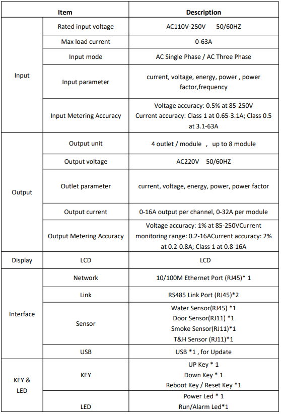
2.2 Scope of application
1. Apply to server cabinets and network cabinets etc
2. The current range for each channel is 0-16A. Each module of the current range is 0 to 32A
2.3 Installation
1. Vertical installation
2. Horizontal installation
2.4 Interface Description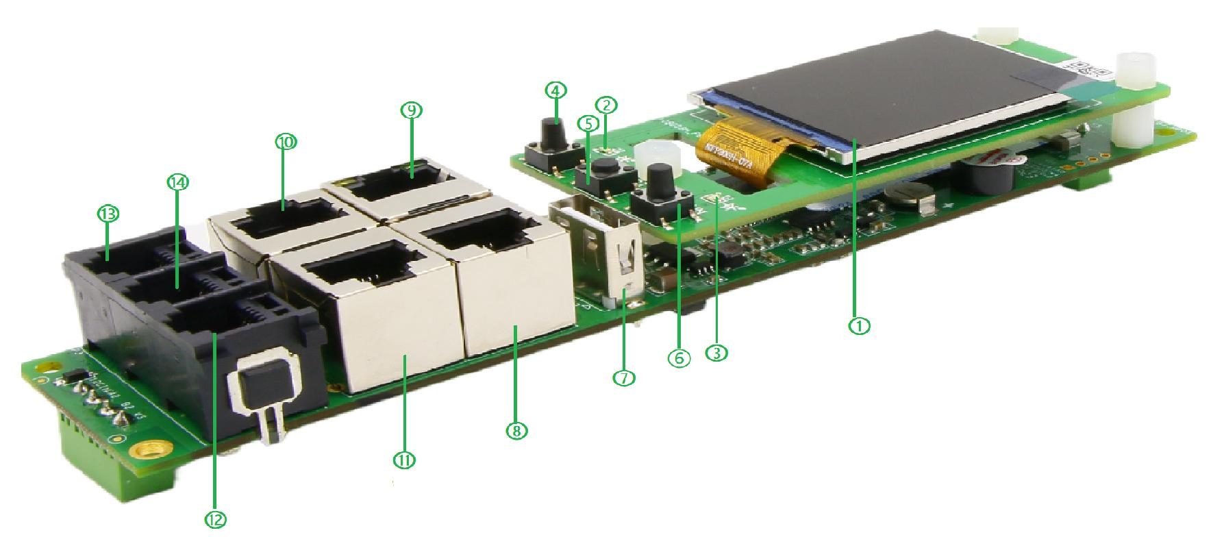
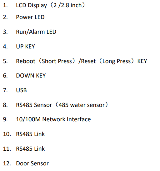
2.4.1 LED Indication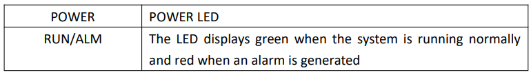
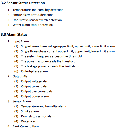
2.4.2 Alarm & Sound & LCD
When the PDU detects the following conditions:
1.The input is abnormal, for example, the electrical parameter exceeds the limit
2.The output is abnormal, for example, the electrical parameter exceeds the limit
3.The sensor parameters are abnormal, for example, the temperature and humidity
exceed the limit
The alarm will be triggered, and the alarm LED will display red, and the corresponding
parameter line on the LCD screen will be marked red
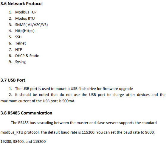
2.4.3 Device Cascade
1.Set one PDU work as Master and others work as Slave
2.Connect the RS485 Link out interface of the Master PDU to the RS485 Link interface of
the Slave#1 PDU
3.Connect the RS485 Link out interface of the Slave#1 PDU to the RS485 Link interface of
the Slave#2 Machine . Connect as below.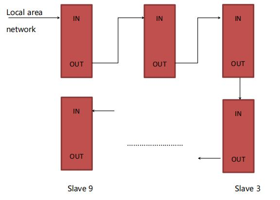
4.In this way, PDUs are cascaded with one master and nine slave. Log in to the Master
system through the web browser of a PC or other ways to monitor and control devices
and cascade successfully
2.4.4 Note
1.The interval between powering on and off the device is about 15seconds. Avoid damage
to the device, please do not frequently power on or off
2.Ensure that proper devices are connected to all interfaces of the PDU. For example, the
PDU is connected to other network devices through network cables. The LINK port is used to
cascade the master and slave RS485 devices, and PDU is connected to sensor devices through
sensor ports
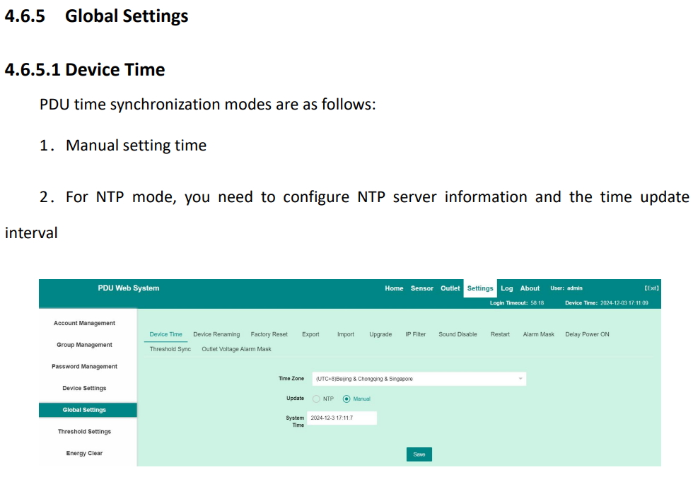
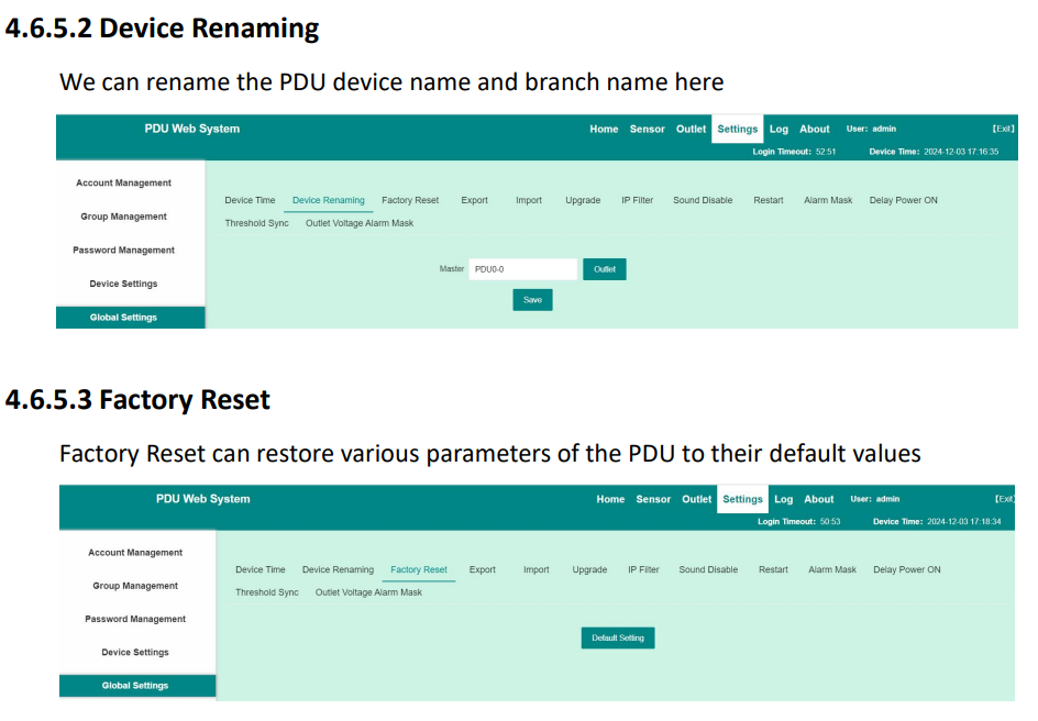
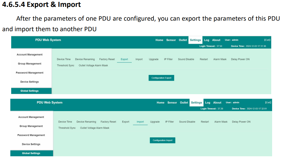
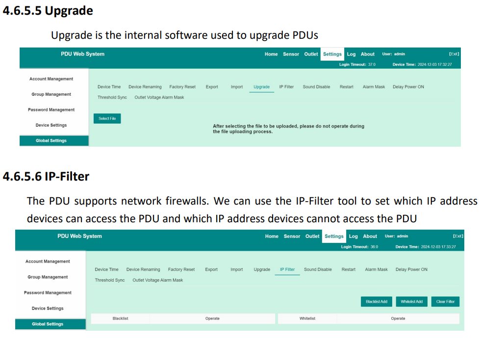
3. System Function Description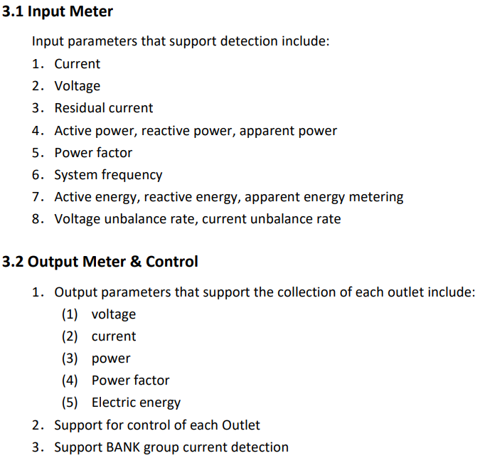
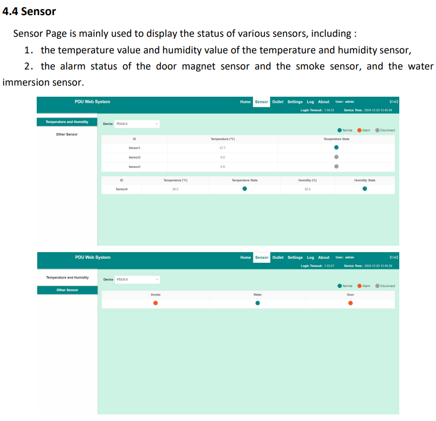
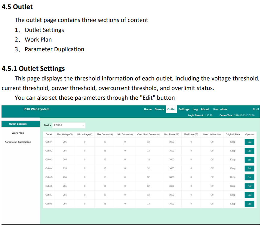
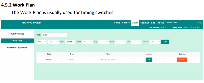
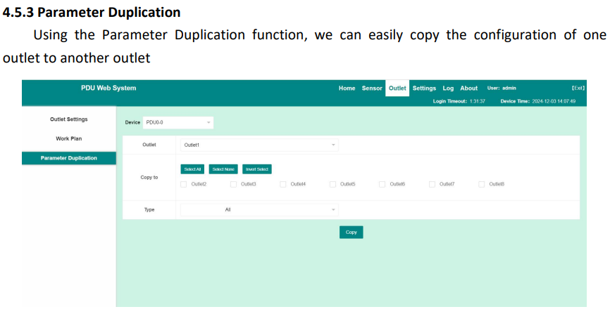
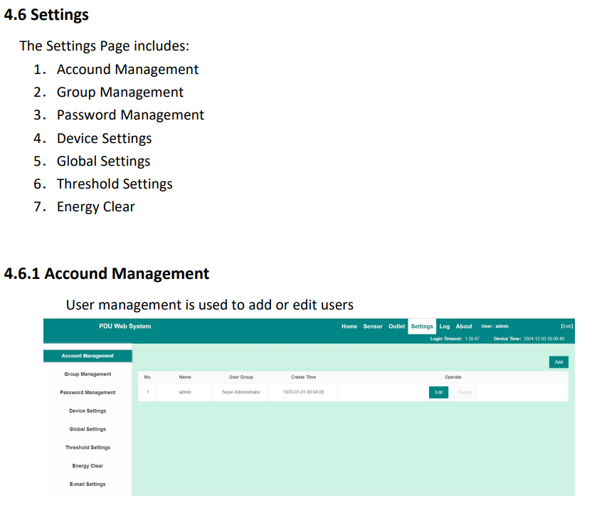
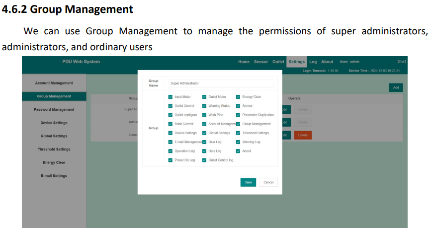
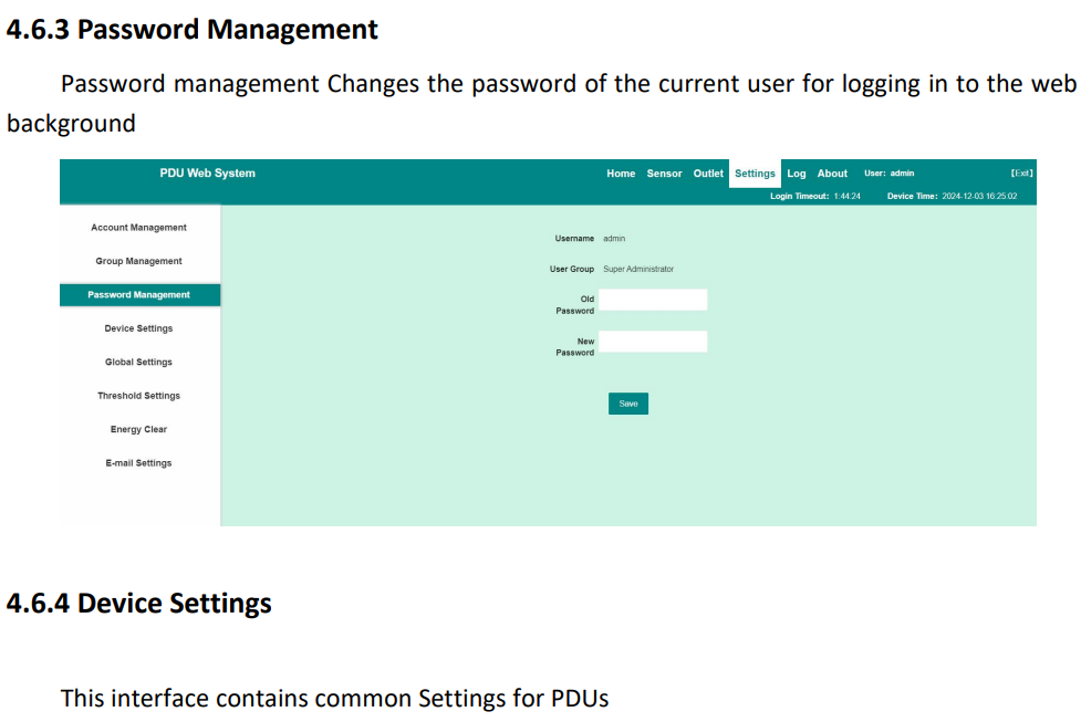
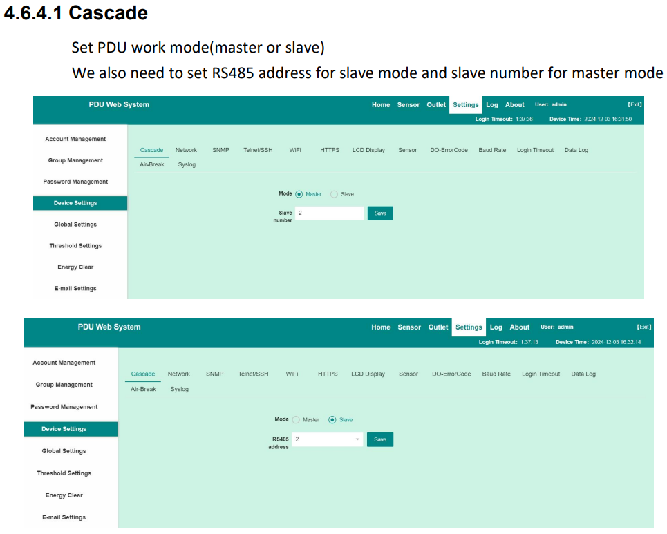
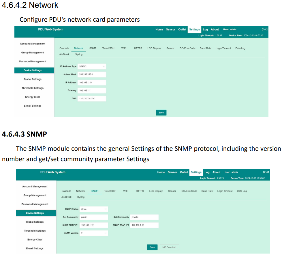
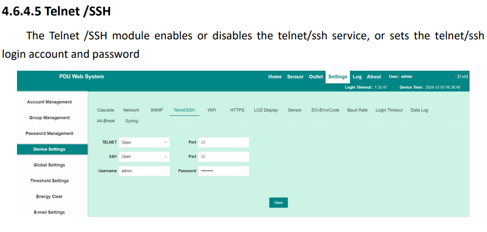
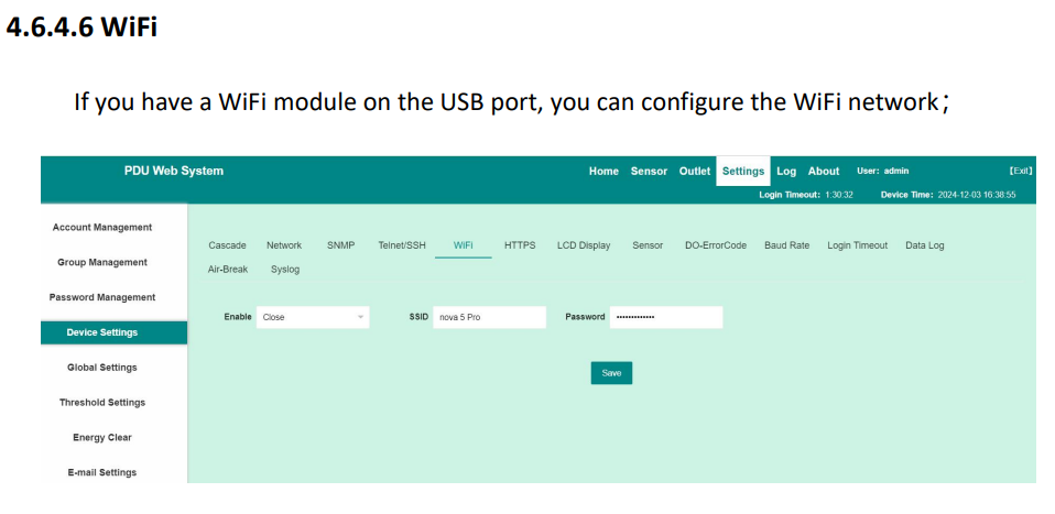
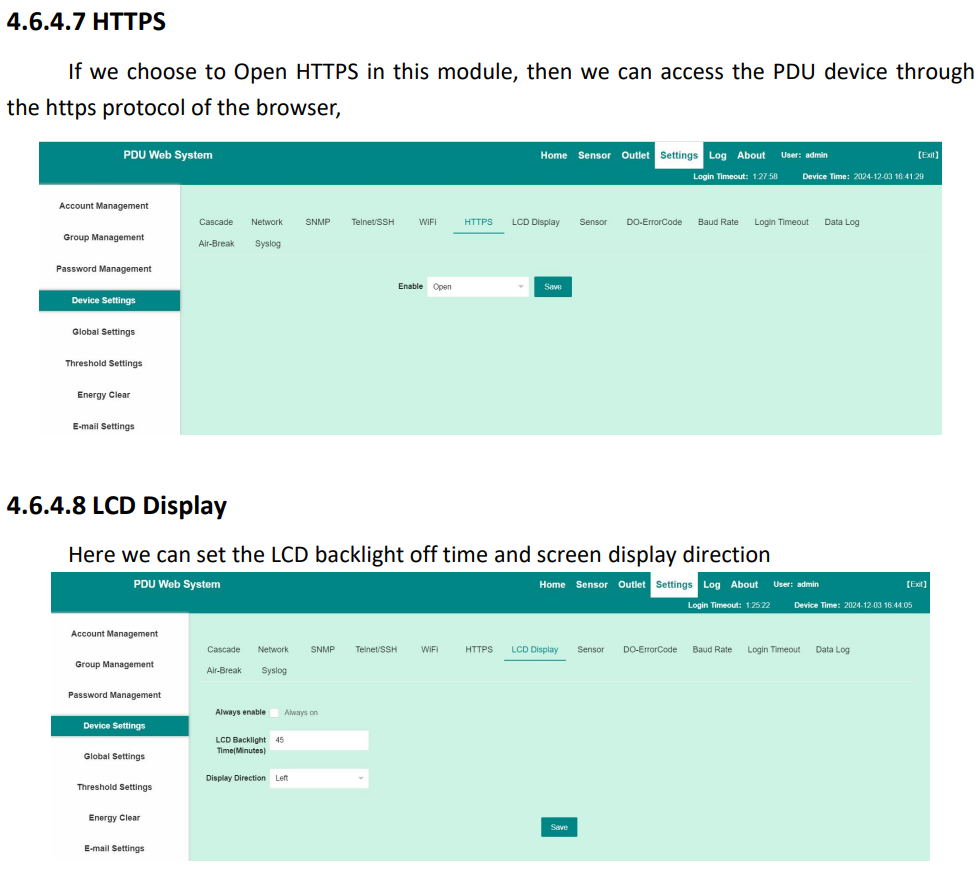
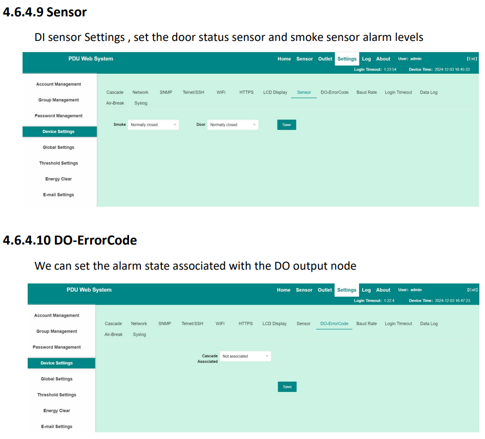
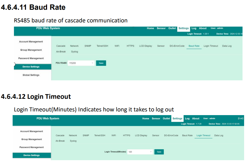
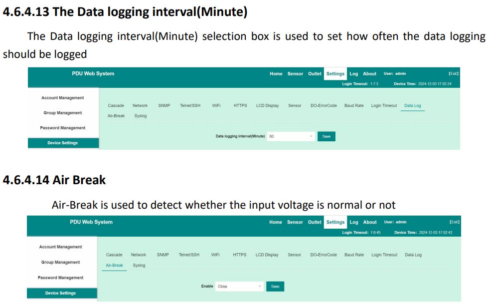
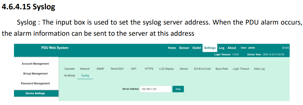
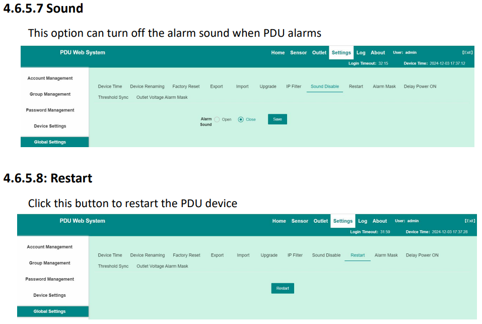
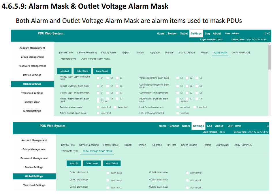
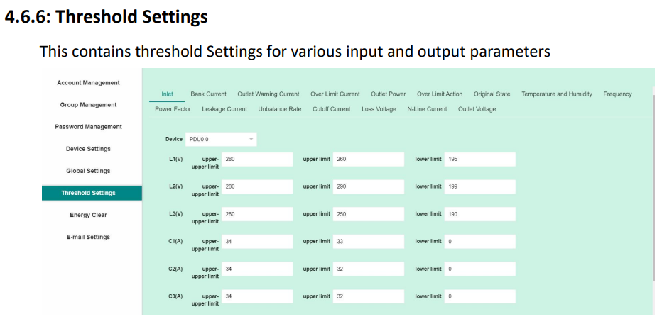
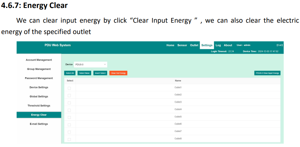
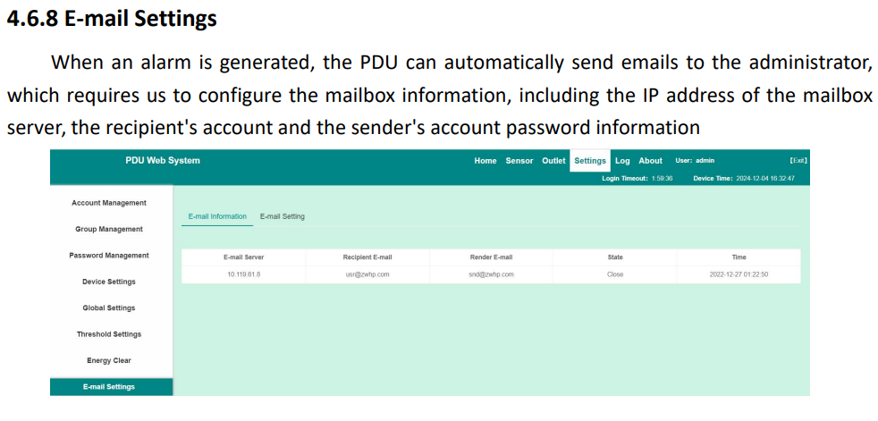
![]()