
06
11/2026
Smart PDU and Sensor Integration for Edge Cabinets: An Application Guide
An application guide to planning a Smart PDU alongside BM-CGQ07, BM-CGQ06, BM-CGQ04 and BM-CGQ05 sensors in edge cabinets, covering RS-485 Modbus and dry-contact design.
Smart PDU and Sensor Integration for Edge Cabinets: An Application Guide
Edge cabinets fail in two unrelated ways, and most deployments only watch one of them. The first is electrical: a device stops drawing power, an outlet trips, or a circuit drifts outside tolerance. The second is physical: water reaches the cabinet floor, a door stays open and the heat load changes, or smoke appears before any temperature alarm triggers. This guide plans both layers together for edge and remote cabinets.
The power layer uses a Smart Power Distribution Unit — the BOMPDU Intelligent 2nd generation PDU, with RS485 Modbus communication, per-channel output measurement, and settable overvoltage, undervoltage and overcurrent alarms. The environment layer uses four BOMPDU sensors: the BM-CGQ06 Water Leak Detector (RS-485, MODBUS), the BM-CGQ07 Door Sensor (dry contact), the BM-CGQ04 Temperature & Humidity Sensor (I²C), and the BM-CGQ05 Smoke Detector (wired alarm output).
BOMPDU is the brand of Wuxi Bom Electronic Technology Co., Ltd., a Wuxi, Jiangsu–based manufacturer established in 2018 that develops, produces and sells end-of-row power distribution solutions for data centers. Its main products are the Intelligent 2nd generation PDU and the 1U_1.5U 485 PDU.
The power layer of an edge cabinet: a BOMPDU Intelligent 2nd generation PDU with RS485 Modbus communication and a segment code LCD display.
Problem Definition: What an Unmonitored Edge Cabinet Cannot Tell You
An edge cabinet is a small, usually unmanned enclosure that places compute, network or control equipment close to where data is generated. Because nobody is standing next to it, every condition that matters has to be reported, not observed. Four information gaps repeat across almost every edge design.
- Input power state. Without measurement, a cabinet reports only “powered” or “dark”. It cannot show whether input voltage has moved outside tolerance or whether load current has climbed.
- Outlet-level behaviour. Without per-channel measurement, a single misbehaving device can be identified only by unplugging things in sequence during a site visit.
- Physical environment. Temperature, humidity, water and smoke are invisible to a power device. They need their own sensing layer.
- Access state. A door that was closed at commissioning may be open at 02:00, and a dry-contact switch is the simplest way to detect that.
The integration trap is assuming one device closes all four gaps. A Smart PDU distributes, measures and switches power; it is not a general-purpose I/O controller. In the available BOMPDU documentation the Intelligent 2nd generation PDU is specified with RS485 Modbus communication, input and output parameter collection, and separate monitoring and control per output channel — but it is not documented as a sensor gateway that reads I²C devices or dry contacts.
Industry Background: Why Edge Cabinets Need Both Power and Environment Data
Smart power distribution is no longer a premium option inside the category. Research and Markets, in its Power Distribution Unit industry research covering 2024–2030, reports that intelligent PDUs accounted for 55% of total PDU market revenue as of 2023. MarketsandMarkets projects the data center PDU market to reach USD 14.23 billion by 2032, with the intelligent PDU segment growing at a 19.5% CAGR from 2026 to 2032. Both figures are commercial research estimates rather than regulatory data, but they point in the same direction: measurement and remote control are now baseline expectations, not differentiators.
Compliance expectations have moved as well. IEC 62368-1:2023 is the safety standard applied to ICT and AV equipment, including PDUs, in most major jurisdictions. That matters for an edge rollout because the same cabinet design is often replicated across regions, and a sensor package that changes the enclosure, wiring or power entry can change the compliance question.
Operationally, edge cabinets are expected to run continuously. In BOMPDU's documented application data, data center, telecom base station, transportation, government command and manufacturing deployment scenarios are all described as 24/7 continuous operation. Continuous operation is exactly the condition under which an undetected environmental excursion becomes an outage rather than an incident.
Scale also matters. Wuxi Bom Electronic Technology Co., Ltd. operates a 5,000 m² manufacturing facility with approximately 70 staff and an annual production capacity of 10,000 units, supported by an R&D team of 12 engineers and more than ten invention patents for PDU products; production complies with ISO 9000 and ISO 14000. For a multi-site edge rollout, that is the kind of supply base that can absorb cabinet-by-cabinet variation in outlet count and channel configuration.
Detailed Solution: How a Smart PDU and Four Sensors Fit Together
The integration works because each component occupies a different, well-defined role. Power is measured and switched at the PDU. Water, door state, temperature/humidity and smoke are measured by dedicated sensors. The design task is to decide how each sensor's signal reaches the supervisory layer, and what the system is allowed to do automatically when a threshold is crossed.
The power layer: Intelligent 2nd generation PDU
The Intelligent 2nd generation PDU is a Smart PDU specified for data center and cloud computing scenarios. Its rated input voltage is AC110–250 V, 50/60 Hz, with single-phase or three-phase power input and a maximum load current of 0–63 A. Voltage measurement covers 90–264 V (rated input 100–240 V) at stated accuracy Level 1 (1% ± 0.1); current is measured through an external transformer at the same stated accuracy class.
On the output side, the auxiliary module provides four outputs and the main module supports up to eight auxiliary modules. Rated output voltage is AC220 V, 50/60 Hz, with a single-channel maximum of 16 A and a single-board maximum of 32 A. Output parameter collection covers current, voltage, electrical energy and power (active, reactive, apparent and power factor), and output current monitoring spans 0.2–16 A with 2% accuracy in the 0.2–0.8 A band and 1% accuracy in the 0.8–16 A band. Outputs support separate monitoring and control.
Two design details follow directly from those numbers. First, 0.2 A is the bottom of the output monitoring range, so very low-draw devices sit outside it — plan outlet grouping accordingly rather than expecting a reading on every port. Second, single-channel 16 A against a 32 A board limit constrains how many high-draw devices can share one board.
For smaller or lower-density edge cabinets, the 1U_1.5U 485 PDU provides the same measurement-and-alarm logic in a compact rack format: rated input 100–240 V with a 90–264 V working range, RS485 interface with Modbus protocol, a segment code LCD display, and overvoltage, undervoltage and overcurrent alarms with settable parameters.
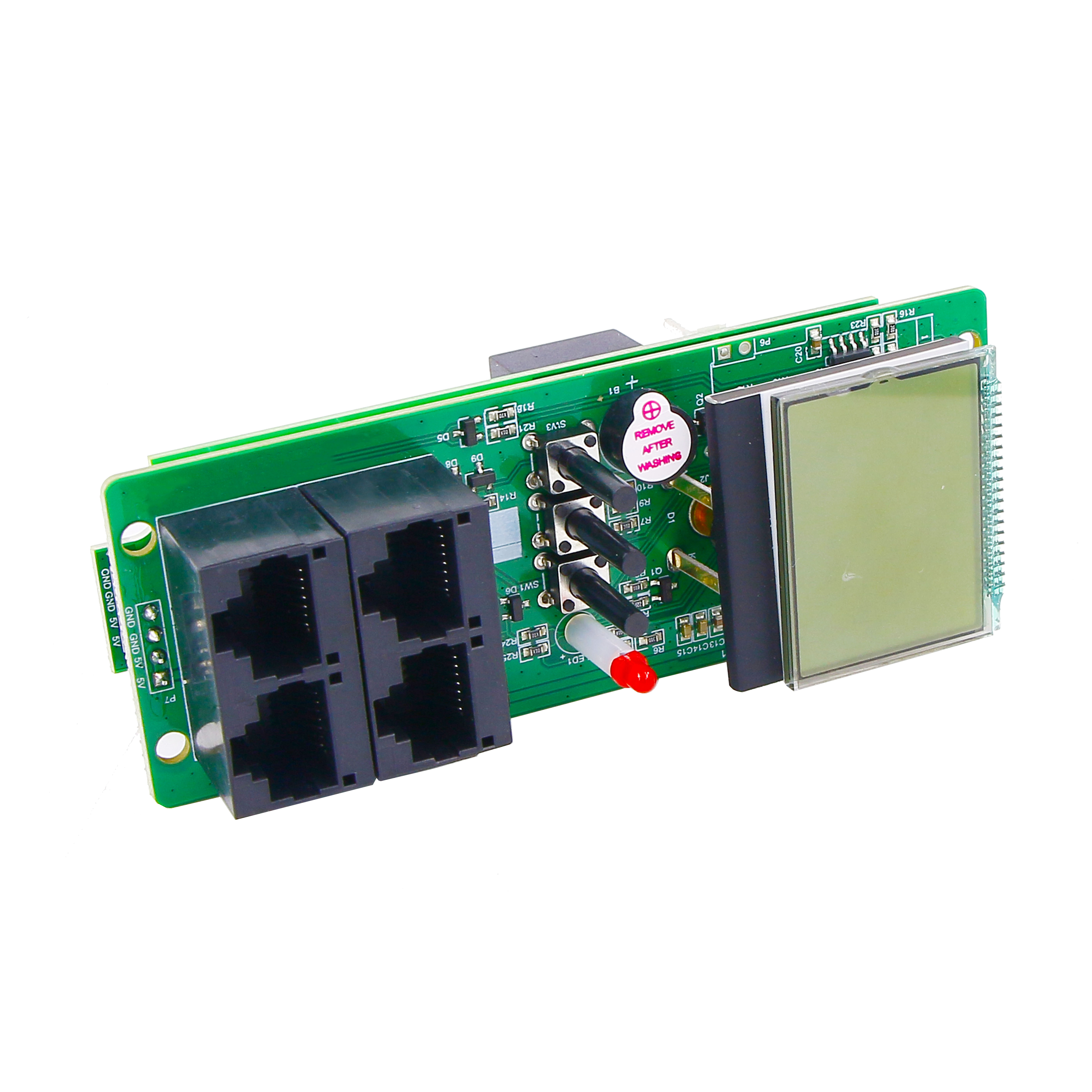
The 1U_1.5U 485 PDU offers RS485 Modbus communication and settable overvoltage, undervoltage and overcurrent alarms in a compact format.
The leak layer: BM-CGQ06 Water Leak Detector
The BM-CGQ06 is a leak detection controller housed in white PVC plastic, powered at 12 V DC with 3 W consumption. It communicates over an RS-485 interface using MODBUS protocol, reaching up to 1,200 m without a repeater, and supports a maximum sensor cable length of 500 m. It also provides an SPDT relay output with normally-open or normally-closed configuration.
That combination is the reason the leak detector anchors the sensor plan. It is the only one of the four sensors with a native RS-485 Modbus interface, which places it in the same protocol family as the Smart PDU. It is also the only one with a relay output, which means it can drive a local action — a beacon, a contactor, a BMS input — without waiting for a supervisory system to poll it. It mounts on 35 mm DIN rail, measures 108 × 59 × 37 mm (88 × 59 × 37 mm excluding terminals), weighs 150 g, operates from −25 °C to 50 °C at 5%–90% RH non-condensing, is rated RoHS and industrial grade, and is intended for data center and server room, telecommunications, financial and banking, industrial automation, building management, and energy and power environments.
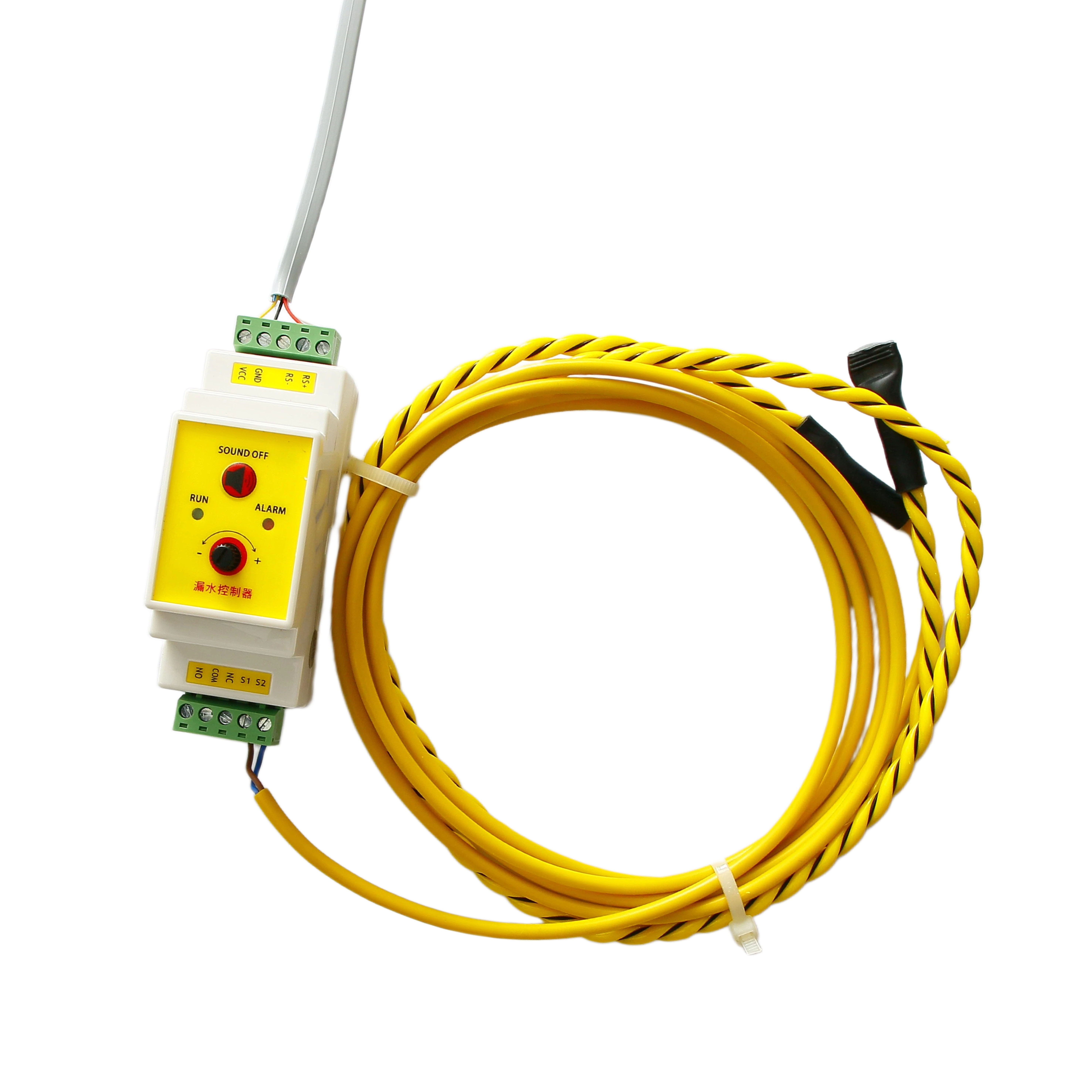
BM-CGQ06 Water Leak Detector: RS-485 MODBUS communication, SPDT relay output, 35 mm DIN rail mounting, up to 500 m sensor cable.
The door layer: BM-CGQ07 Door Sensor
The BM-CGQ07 is a dry contact sensor with an ABS plastic housing and an embedded permanent magnet. Its contact type is dry contact, configurable as normally open or normally closed, operating at 5–30 V DC with a maximum switching current of 100 mA, contact resistance below 100 mΩ in the closed state and insulation resistance above 100 MΩ in the open state. Actuation gap is ≤ 15 mm, cable length is 1 m as standard and customizable, and the protection rating is IP40. It is intended for data center and server room, security and access control, and building automation applications.
Because the output is a genuine dry contact, the door sensor does not need a protocol. It needs a digital input with a wetting voltage inside the 5–30 V DC window and a pull-up or pull-down that keeps leakage current well under 100 mA. Choose normally-closed wiring if the monitoring system should also flag a cut or disconnected cable as an alarm state.

BM-CGQ07 Door Sensor: configurable normally-open or normally-closed dry contact, ≤ 15 mm actuation gap, IP40.
The environment layer: BM-CGQ04 Temperature & Humidity Sensor
The BM-CGQ04 is a digital temperature and humidity sensor built on a semiconductor silicon-based capacitive humidity sensor with an on-chip temperature sensor. Its interface is I²C (standard protocol) at 2.2–5.5 V DC, with 250 nA sleep current and 980 µA measuring current. Humidity range is 0–100% RH with ±3% RH typical accuracy at 25 °C and 3.3 V; temperature range is −40 °C to 80 °C with ±0.5 °C typical accuracy at the same conditions. It is fully calibrated at the factory, carries JEDEC JESD22-A114 ESD protection (HBM ±4 kV), ships as an SMD part in 50-piece trays and 100-piece bags, and weighs approximately 0.9 g.
The practical consequence is architectural, not cosmetic. This sensor is a board-level component, not a bus device: it cannot be dropped onto an RS-485 segment alongside the PDU and the leak detector. It needs a host controller that reads it over I²C and republishes the values into the supervisory layer. Plan that controller early — it is the piece most often discovered late in an edge cabinet build.
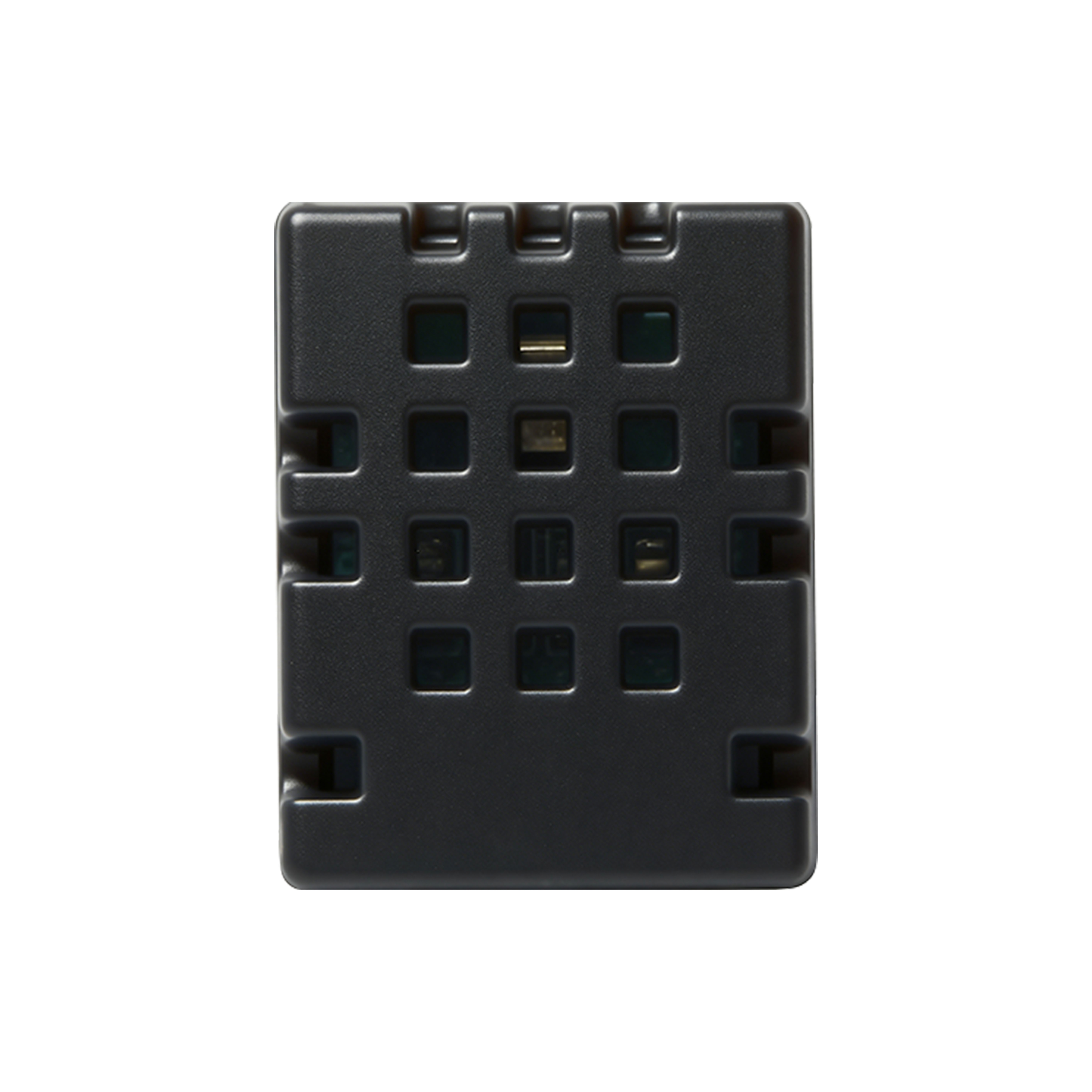
BM-CGQ04 Temperature & Humidity Sensor: I²C interface, 0–100% RH, −40 °C to 80 °C, factory calibrated.
The smoke layer: BM-CGQ05 Smoke Detector
The BM-CGQ05 is a wired smoke detector using photoelectric/optical sensing, powered at 10–35 V DC, with an LED indicator for alarm status and an alarm signal output. It is wired in a 2-wire or 4-wire configuration and mounts on a wall or ceiling with a standard base. The housing is ABS plastic, and the specification lists an industrial-grade application standard. It is intended for commercial buildings, industrial facilities, warehouses and logistics, data centers, hospitality and retail, and fire safety and security systems.
The alarm output is the integration point, and it should be confirmed as a signal type before wiring. If the output is a dry contact, it lands on a digital input exactly like the door sensor. If it is a voltage or current-loop signal, the input module must match it. Confirm this at model level rather than assuming.
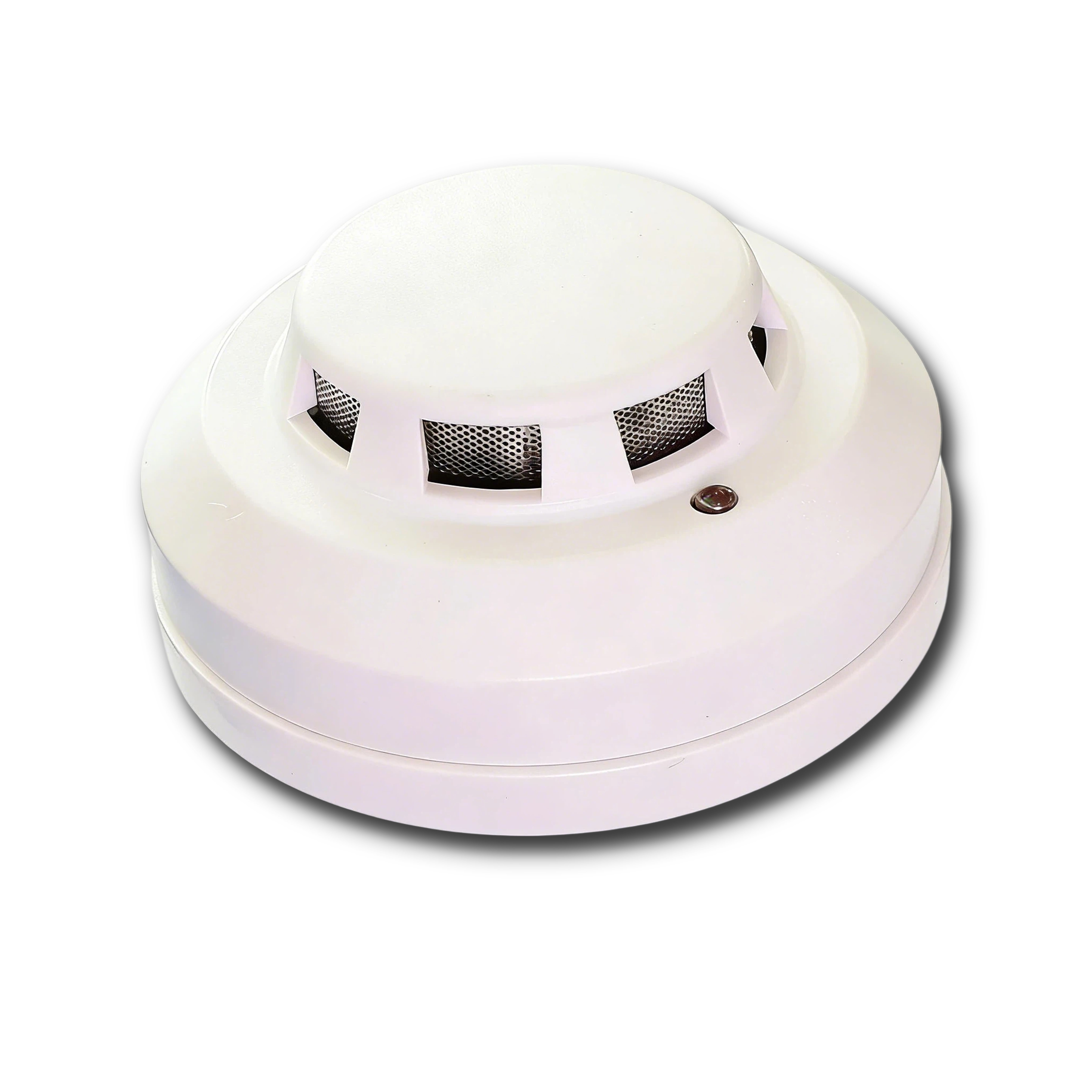
BM-CGQ05 Smoke Detector: wired, 10–35 V DC, photoelectric sensing, alarm signal output, 2-wire or 4-wire wiring.
Step-by-Step Breakdown: Planning a Cabinet From Load to Alarm
Use Cases: Where This Combination Fits
Telecom and outdoor-adjacent shelters. BOMPDU documents telecom base station support as a 24/7 application requiring remote reboot and voltage/current monitoring, with wide temperature range and lightning protection as site requirements. A Smart PDU plus the BM-CGQ06 leak detector and BM-CGQ04 temperature/humidity sensor fits the power and environment questions. Note the sensor limits: the BM-CGQ06 operates from −25 °C to 50 °C, so it belongs in a sheltered or conditioned enclosure, not an unprotected outdoor compartment.
Roadside and traffic cabinets. Intelligent traffic system projects are documented as needing centralized power control and status feedback, surge protection and rail-mount installation, supporting cameras, optical transceivers and industrial PCs. The DIN-rail BM-CGQ06 suits this format directly, and the door contact adds tamper and access visibility at an unattended roadside location.
Small IDC and satellite server rooms. Data center deployments are documented around remote power control, energy consumption monitoring and remote reset, with servers, switches, UPS and environment monitoring units as supporting equipment. This is the case where the temperature/humidity layer carries the most weight, because cooling capacity at a satellite room is usually the first constraint to be reached.
Government and emergency command micro-sites. Command system construction is documented as requiring hierarchical power management and fault alarm, dual power input, high reliability and alarm notification. Layering the smoke detector and door contact onto the PDU alarm path supports that requirement without adding a separate panel.
Industrial cells and automation upgrades. Manufacturing deployments are documented around RS485 power control and status collection with PLC, touch screen and sensor equipment, where Modbus-RTU and strong anti-interference are the stated requirements. In this environment the wired, bus-based sensors integrate most cleanly, and electromagnetic conditions should be reviewed before commissioning.
Comparison Table: Sensor Signals and Power-Side Specifications
Table 1 — Signal classes across the five components. Everything below is taken from the BOMPDU product specifications.
| Layer | Model | Interface / output | Key electrical fact | Planning consequence |
|---|---|---|---|---|
| Leak | BM-CGQ06 | RS-485, MODBUS; SPDT relay (NO/NC optional) | 12 V DC, 3 W; up to 1,200 m RS-485 without repeater; 500 m max sensor cable | Can share a Modbus supervisory segment; relay enables a network-independent local action |
| Door | BM-CGQ07 | Dry contact, NO/NC configurable | 5–30 V DC; max switching current 100 mA; ≤ 15 mm actuation gap; IP40 | Needs a digital input, not a bus; wire NC to make a cut cable read as an alarm |
| Temperature & humidity | BM-CGQ04 | I²C (standard protocol) | 2.2–5.5 V DC; 0–100% RH; −40 °C to 80 °C; ±3% RH and ±0.5 °C typical | Board-level part: requires a host controller before it can reach any supervisory layer |
| Smoke | BM-CGQ05 | Wired, alarm signal output | 10–35 V DC; photoelectric sensing; 2-wire or 4-wire | Confirm whether the output is a dry contact or a voltage signal before wiring |
| Power | Intelligent 2nd generation PDU | RS485, Modbus | AC110–250 V, 50/60 Hz; single or three-phase input; 0–63 A max load | Provides the measurement and alarm backbone the sensor data is aggregated against |
Table 2 — Power-side feature checklist for an edge RFQ. The middle column reflects what the available BOMPDU documentation states; the right column lists what still has to be confirmed in writing at model level.
| Requirement area | Stated in available documentation | Confirm before ordering |
|---|---|---|
| Remote control | Outputs support separate monitoring and control; remote power control and remote reset described for data center applications | Per-channel switching method, fail-safe state after power loss, permission model |
| Socket-level monitoring | Per-output current, voltage, energy and power collection; current range 0.2–16 A | Reading behaviour below 0.2 A and polling granularity |
| IPv6 support | Not stated for this PDU; RS485 Modbus is the stated interface | Whether an IP-based management option exists for the required model |
| Sequential power-on | Not stated | Whether staggered outlet energisation is available, and in what order logic |
| Single/three-phase input | Single-phase or three-phase power input stated | Phase configuration of the exact ordered model and matching breaker |
| Custom alarm thresholds | Overvoltage, undervoltage and overcurrent alarms with settable parameters | Threshold ranges, hysteresis, and whether sensor-type events can enter the same alarm table |
| Cascadable master-slave | Main module supports up to eight auxiliary modules, each with four outputs | Whether PDU-to-PDU cascading is supported, and the exact topology and addressing |
| Network management | RS485 Modbus stated; SNMP is listed as a data center deployment requirement, not as a stated PDU interface | Which management interfaces ship with the ordered model |
| Industrial deployment | Industrial automation listed as an application, with Modbus-RTU and anti-interference as stated requirements | Cabinet-level EMC environment and shielding practice |
FAQ
Which compliance points should be closed before an edge cabinet sensor package is released?
Start with the power path. IEC 62368-1:2023 is the safety standard applied to ICT and AV equipment, including PDUs, in most major jurisdictions, so the PDU model and its enclosure integration should be checked against it for each destination market. On the sensor side, the BM-CGQ06 Water Leak Detector is stated as RoHS certified and industrial grade, and the BM-CGQ05 Smoke Detector is listed against an industrial-grade application standard. Manufacturing for the PDU line complies with ISO 9000 and ISO 14000. National deviations and any fire-code requirement for the smoke device must be verified per project — the available documentation does not publish certificate numbers, so request the current certificates with the quotation.
Can the water leak detector and the Smart PDU share a single RS-485 Modbus segment?
They are protocol-compatible, which makes a shared segment a reasonable design intent. The BM-CGQ06 uses an RS-485 interface with MODBUS protocol and reaches up to 1,200 m without a repeater, with a maximum sensor cable length of 500 m. The Intelligent 2nd generation PDU communicates over RS485 with Modbus protocol as well. What must be confirmed before wiring is device-level: register map, supported baud rate and parity, address range, termination and biasing practice, and the polling interval the controller will use. The PDU register map is not included in the published documentation, so request it in writing rather than discovering it during commissioning.
What is the minimum bill of materials for one monitored edge cabinet, and what drives the cost?
A workable minimum is one Smart PDU sized to the load, one BM-CGQ06 Water Leak Detector on DIN rail, one BM-CGQ04 Temperature & Humidity Sensor plus its host controller, and a door contact using the BM-CGQ07. Smoke detection via the BM-CGQ05 is added where the site or insurer requires it. The cost drivers are outlet count and board count (each auxiliary module provides four outputs, up to eight modules on the main module), phase configuration, spare capacity against the 16 A per-channel and 32 A per-board limits, leak cable length up to the 500 m maximum, and whether the smoke device is inside scope. No unit prices, MOQ or landed-cost figures are published in the available documentation; those must come from a project-specific quotation.
How should a pilot cabinet be validated before a multi-site rollout?
Build one cabinet and test each layer physically rather than on a bench. Open the door and confirm the BM-CGQ07 dry contact changes state; wet the leak cable and confirm both the RS-485 MODBUS reading and the SPDT relay action; apply controlled heat and confirm the BM-CGQ04 readings respond and are republished by the host controller; trigger the BM-CGQ05 with test aerosol and confirm the alarm output is read correctly. Then run the cabinet for 24 hours under normal load, log the Modbus polling, and record baseline voltage, current, temperature and humidity values. That baseline becomes the reference for every later site. Sample units and configuration-matched pilot builds can be requested directly from BOMPDU for this stage.
What should be confirmed about lead time and supply before committing to a rollout?
Supply capacity is documented: Wuxi Bom Electronic Technology Co., Ltd. operates a 5,000 m² facility with approximately 70 staff and an annual production capacity of 10,000 units, supported by 12 engineers in R&D and more than ten invention patents for PDU products. Specific lead time, batch sequencing and delivery schedule are not published in the available materials, so they must be quoted against the actual outlet configuration and quantity. For a rollout, request a written schedule per cabinet variant rather than a single blended figure, because the outlet plan and phase configuration differ between sites. Contact tony1091803@wxbom.cn or +86 18751550927, or download the BOMPDU product brochure to start a configuration review.
Conclusion
Edge cabinet availability depends on two layers that are usually planned by different people: the power layer that measures, switches and alarms, and the environment layer that senses water, door state, temperature/humidity and smoke. Bringing them into one design pass is what makes a remote cabinet observable.
The architecture that follows from the BOMPDU documentation is straightforward. The Intelligent 2nd generation PDU, or the compact 1U_1.5U 485 PDU for lower-density cabinets, provides measured power distribution over RS485 Modbus with settable overvoltage, undervoltage and overcurrent alarms. The BM-CGQ06 Water Leak Detector joins that Modbus world directly and adds a relay for network-independent action. The BM-CGQ07 Door Sensor delivers a configurable dry contact for access state. The BM-CGQ04 Temperature & Humidity Sensor supplies calibrated environmental readings over I²C and requires a host controller. The BM-CGQ05 Smoke Detector closes the fire layer through its alarm output.
Three details decide whether the build succeeds: treating I²C as a board-level interface rather than a bus, confirming the smoke output type before wiring, and obtaining register maps and threshold behaviour in writing before commissioning. Get those right and the cabinet reports its own condition; get them wrong and the cabinet stays silent until someone visits it.
Planning an edge cabinet rollout?
Send your load list, phase configuration and sensor scope to BOMPDU and request a matched PDU and sensor sample set for pilot validation. Email tony1091803@wxbom.cn, call +86 18751550927, or message WhatsApp.
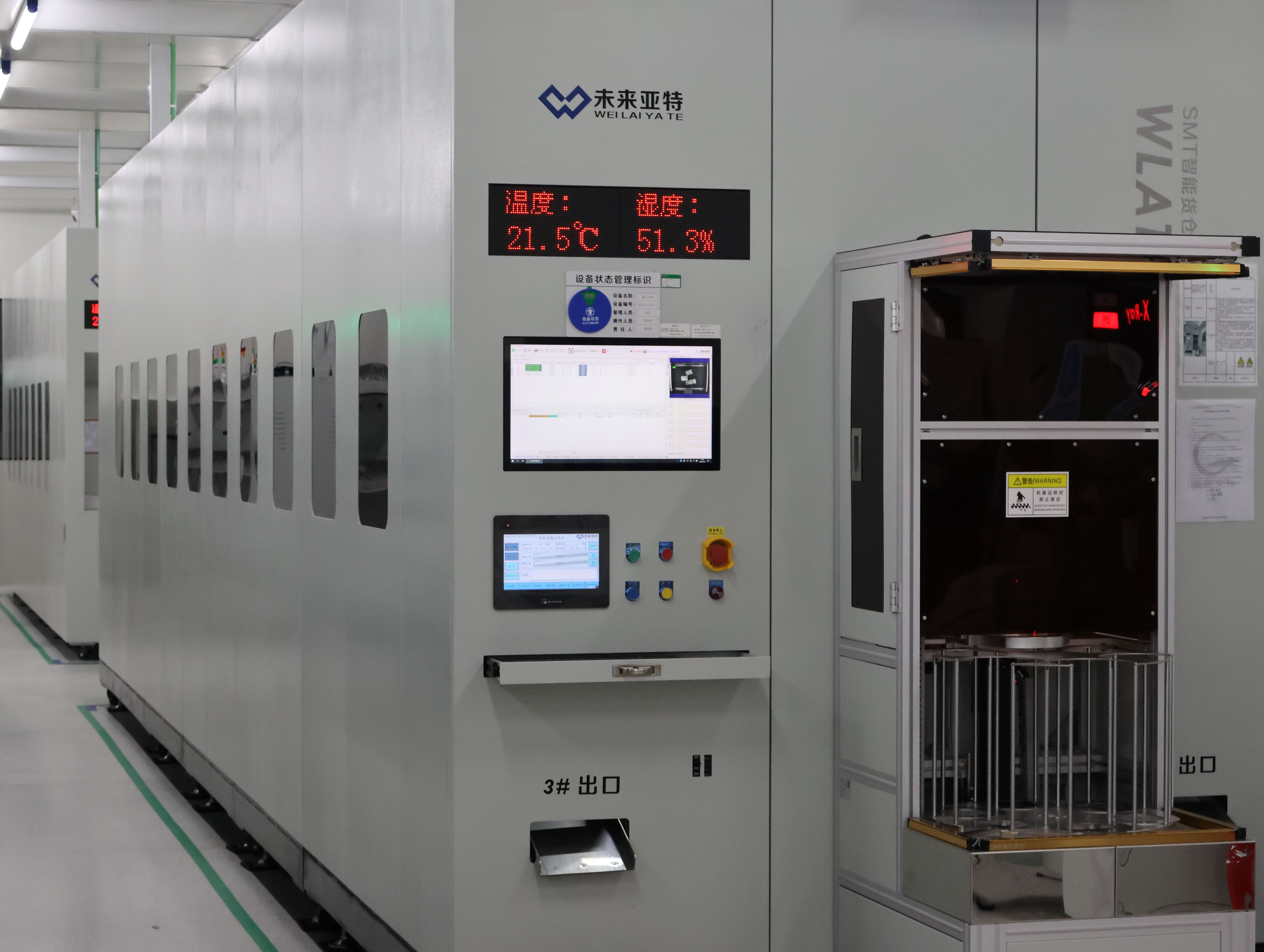
Batch supply for multi-site rollouts: BOMPDU's warehousing system at the Wuxi facility, which covers 5,000 m² with an annual capacity of 10,000 units.
Market figures cited in this guide are commercial research estimates (Research and Markets via BusinessWire, 2024; MarketsandMarkets, 2025) and are used for context only. Product specifications are as published in BOMPDU product documentation; confirm model-level details with the supplier before ordering.