10
11/2026
Retrofitting Smart PDU Monitoring into an Existing Rack: A Practical Plan
A practical retrofit plan for adding Smart PDU monitoring to an existing rack: inventory, RS485 Modbus design, sensor mapping, acceptance checks and ISO 9001:2015 documentation review.
Retrofitting Smart PDU Monitoring into an Existing Rack: A Practical Plan
A rack already carrying production load can gain smart PDU monitoring without replacing its UPS, its breakers or its cabling. The retrofit works when it is run as five bounded tasks — an as-built rack inventory, a metering-versus-switching decision, an RS485 Modbus segment design, a sensor interface map, and a written acceptance check — instead of as a like-for-like product swap.
This plan is written for buyers and facility engineers in the research-to-evaluation stage of a retrofit project: you know the rack must become measurable and controllable, but the power path itself is not being rebuilt. It uses two BOMPDU rack units as the reference building blocks. BOMPDU is the trading name of Wuxi Bom Electronic Technology Co., Ltd., a Wuxi, Jiangsu-based manufacturer of end-of-row power distribution solutions for data centers, established in 2018, offering an Intelligent 2nd generation PDU line and a 1U/1.5U RS485 PDU line.
The distinction that decides most retrofits is simple. A 1U/1.5U RS485 PDU measures and reports what enters the rack and raises over/under-voltage and overcurrent alarms over an RS485 Modbus link. An Intelligent 2nd generation PDU adds separate monitoring and control of each output channel. Choose the first if the retrofit is about visibility and alarming; choose the second if it is about remote control, socket-level accountability or remote reboot as a Smart Power Distribution Unit function rather than a product label.
Problem Definition: why retrofits stall before the first meter reading
Retrofit projects rarely fail on hardware. They fail on sequencing and on documentation that nobody wrote down before the rack went dark.
- The retrofit is scoped as a product replacement. A team orders a Network Managed PDU, then discovers the upstream circuit, the outlet types and the U-space were never inventoried, so the unit cannot be mounted or fed as assumed.
- There is no pre-change baseline. After installation, nobody can tell whether the new reading of 0.01 kW resolution reflects the load, the meter, or a wiring error, because no before-and-after comparison point exists.
- Monitoring is confused with switching. Input metering answers “how much power is this rack drawing”. It does not answer “which device is drawing it” and it cannot reboot a hung server. Buyers who expect socket-level control from an input-metered unit end up with a data feed and no remediation path.
- Sensors are ordered as a shopping list. A door contact, a leak detector and a temperature sensor are three different interfaces. If the monitoring head has no matching input, the accessories arrive and stay in the box.
- Acceptance is verbal. Without written checks, the retrofit is declared finished the day the LEDs turn on, and the first real alarm is also the first test.
The practical consequence: in an existing rack, the retrofit must be defined by what the power path already is, not by what a catalogue says a smart PDU can do.
Industry Background: why retrofit work now carries the category
Smart rack power is no longer a premium option layered on top of basic distribution; it is becoming the default specification, which is precisely why the installed base — not new-build — is where most retrofit decisions are taken.
- Research and Markets data reported that intelligent PDUs accounted for more than half of total PDU market revenue as of 2023, at 55% (source: Power Distribution Unit Industry Research Report 2024–2030).
- MarketsandMarkets projects the data center PDU market to reach USD 14.23 billion by 2032, with the intelligent segment growing at a 19.5% CAGR from 2026 to 2032.
- IEC 62368-1:2023 is the safety standard applied to ICT and AV equipment, including PDUs, in most major jurisdictions — so any unit introduced into an existing rack sits inside a compliance framework that predates the retrofit.
Two market realities shape retrofit planning. First, feature tiers are not standardised across manufacturers: Server Technology describes its intelligent rack PDUs as spanning smart, switched and monitored-per-outlet configurations, while Vertiv PowerIT documentation distinguishes monitored unit-level from switched outlet-level monitoring. Second, capability claims are not interchangeable across brands: Raritan states PDU-to-PDU cascading up to 16 devices, while Vertiv documentation describes daisy-chaining up to 50 devices on a single IP address. Those two numbers describe different architectures. A retrofit specification that copies a device count without the topology behind it will not survive commissioning.
Detailed Solution: two PDU roles, one bus, one sensor map
The retrofit design in this plan treats the rack as three layers that can be added independently: a metering layer, a control layer, and an environmental layer. The power path — upstream breaker, UPS, feed cable, rack inlet — is not modified, which is what keeps the project small enough to schedule inside a maintenance window.
Layer 1 — input metering and alarms: the 1U/1.5U RS485 PDU
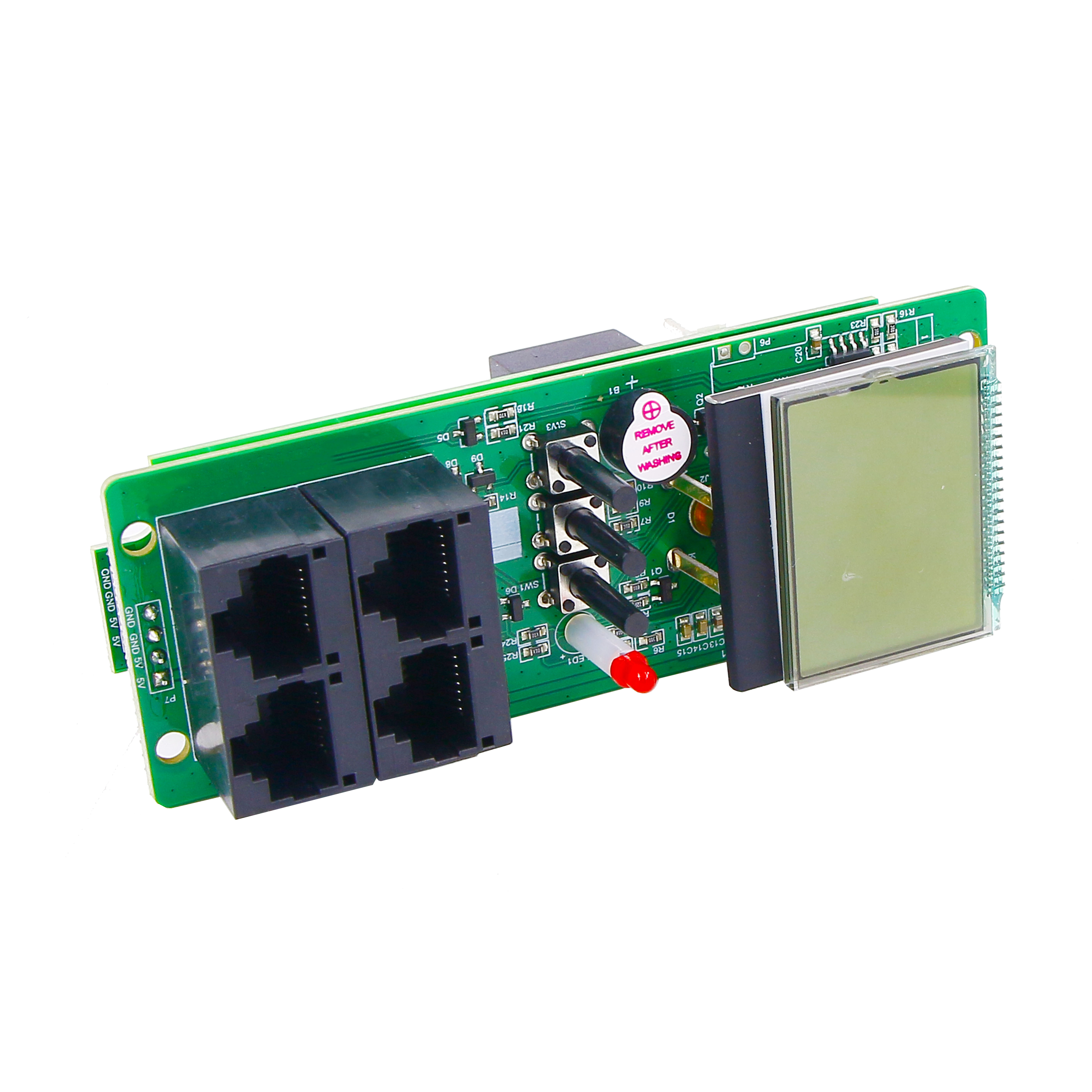
The 1U/1.5U RS485 PDU is the lowest-risk way to make an existing rack measurable. It is a rack-mount Power Distribution Unit with a segment-code LCD (white background, black text) and an RS485 interface running the Modbus communication protocol, so it reports into a bus rather than onto an IP network.
- Rated input voltage 100–240 V, with an input voltage range of 90–264 V; voltage measurement spans 90–264 V with 0.01 V display resolution.
- Current, power and electricity are measured at level 1 accuracy (1% ± 0.1), displayed at 0.01 A, 0.01 kW and 0.01 kWh respectively. Current input uses an external transformer, which is the item to confirm physically during mounting.
- Caution function covers overvoltage, undervoltage and overcurrent alarms, and the parameters can be set — the practical basis for a Custom Alarm Threshold PDU requirement in a retrofit, provided the thresholds are documented rather than left at defaults.
- Housing is metal, plastic and aluminium profile, consistent with a 1U or 1.5U rack allocation.
Layer 2 — socket-level monitoring and control: the Intelligent 2nd generation PDU
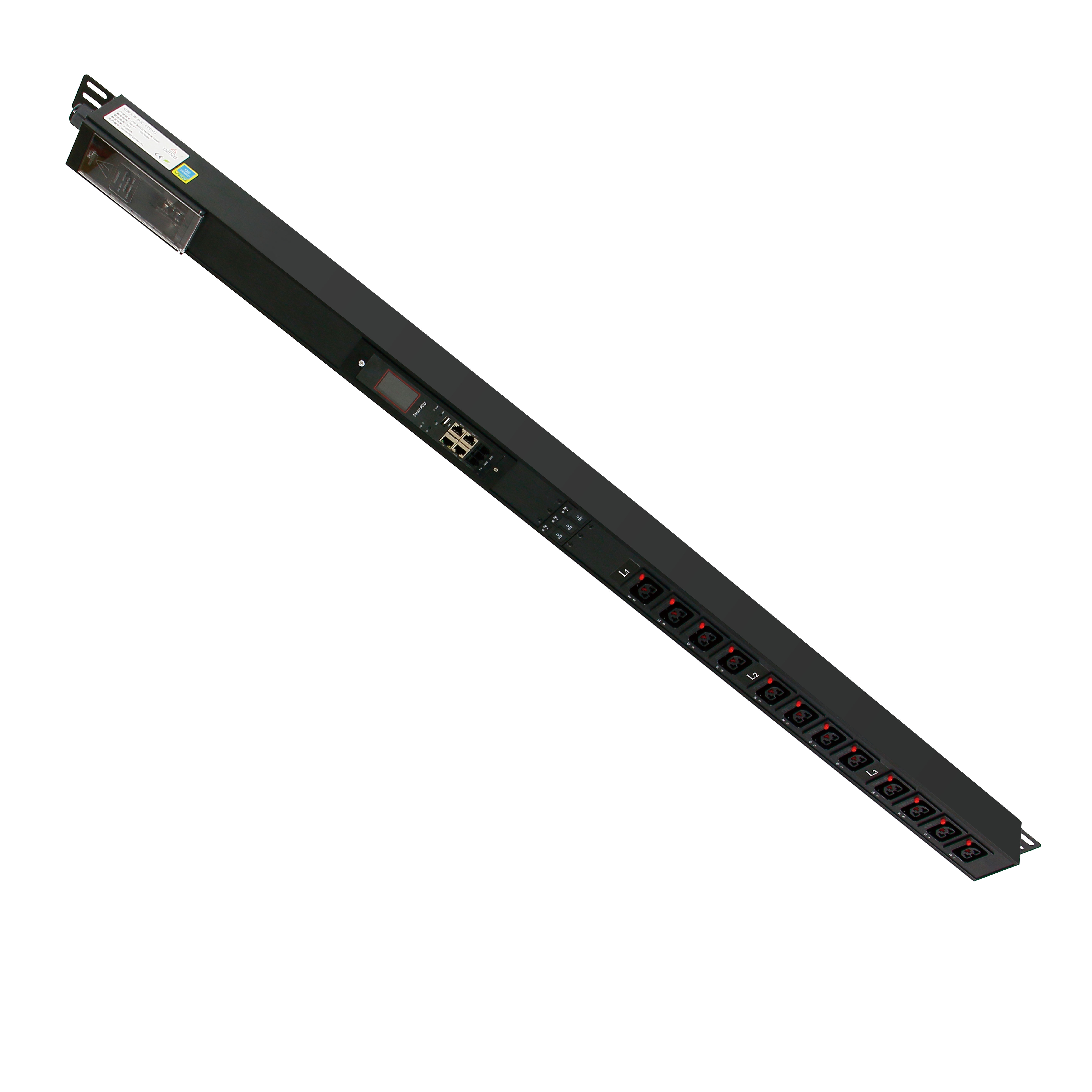
Where the retrofit objective includes remote switching, per-outlet accountability or remote reboot, the Intelligent 2nd generation PDU is the appropriate building block. Its architecture is modular: the main module supports up to 8 auxiliary modules, and each auxiliary module provides 4 outputs.
- Rated input voltage AC 110–250 V, 50/60 Hz; maximum load current 0–63 A; input method is single-phase input or three-phase input — confirm whether the phase configuration you need is a fixed model option or field-selectable before ordering.
- Input collection covers current, voltage, electrical energy and power, including active, reactive and apparent power and power factor. Stated input accuracy: voltage 0.5% across 85–250 V; current level 1 at 0.65–3.1 A and level 0.5 at 3.1–63 A.
- Output collection mirrors the input set at channel level. Rated output current is 16 A maximum per channel and 32 A maximum per board; output voltage accuracy is 1% across 85–250 V, and output current accuracy is 2% at 0.2–0.8 A and 1% at 0.8–16 A, over a 0.2–16 A monitoring range.
- Output function is separate monitoring and control per channel, which is what turns a Network Managed PDU into a Remote Control PDU in day-to-day operations — and what makes a Socket-Level Monitoring PDU claim verifiable at the channel, not the rack.
Layer 3 — environmental sensing on the same segment
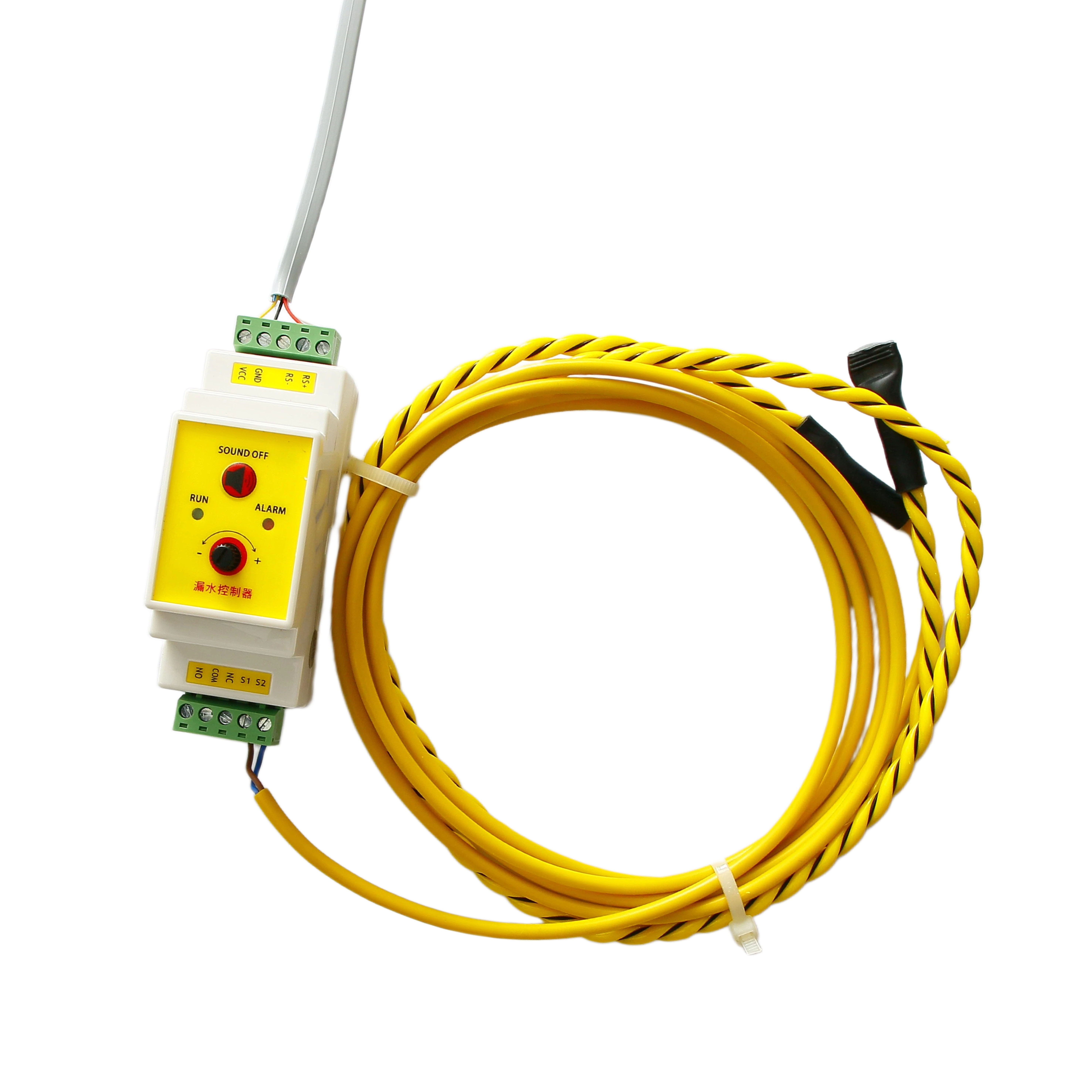
Sensors extend the retrofit from power to condition monitoring, but only where the interface matches. The accessories relevant to a rack retrofit have materially different interfaces, and that difference, not the sensor type, decides the wiring plan.
Step-by-Step Breakdown: eight steps from inventory to sign-off
Step 1 — Build the as-built rack inventory
Walk the rack with a checklist, not a memory. Record: rack U-space available and free U positions; existing PDU form factor and mounting rail type; inlet connector and feed cable rating; upstream breaker rating and whether the feed is single-phase or three-phase; outlet types and counts actually in use; the device list with nameplate current for each load; cord lengths and which outlets are unreachable; and whether the rack is fed from a UPS or raw mains. This inventory decides whether a 1U/1.5U unit fits at all, and it is the document a supplier needs to quote without assumptions.
Step 2 — Record a pre-change baseline
Before any unit is removed, capture the rack's existing electrical condition at idle and at peak: voltage, current per feed, total power, and the time of day each reading was taken. This baseline is the only objective reference for acceptance later. If a clamp meter or the upstream UPS already reports current, note the instrument and its stated accuracy so that the comparison at Step 8 is not made between a precise meter and an unknown one.
Step 3 — Decide monitoring depth and phase configuration
Match the layer to the question. Input metering and alarms map to the RS485 PDU; per-outlet monitoring and switching map to the Intelligent 2nd generation PDU, sized against its 16 A per-channel and 32 A per-board limits and its 4-output auxiliary modules. On phase, decide early: single-phase or three-phase input is a model-level attribute on the Intelligent 2nd generation PDU, and the RS485 unit is rated 100–240 V. Where a Single/Three Phase Switchable PDU is required, confirm the mechanism in writing — a switchable configuration and two fixed variants are different products.
Step 4 — Design the RS485 Modbus segment
The bus is the part of the retrofit most often under-planned. Fix the following before ordering: the physical route of the RS485 cable inside the rack and out to the monitoring head; the device address plan, including every sensor that will share the segment; the register map for each device; and which system polls the bus. Confirm the polling head and its protocol support with the supplier rather than assuming an IP platform can read a serial segment unaided. Where the retrofit must present data as an IPv6 Supported PDU environment, treat IPv6 as a per-model attribute to verify: public manufacturer pages show the capability varies, with Raritan stating IPv4/IPv6 management networking on its intelligent rack PDUs.
Step 5 — Map every sensor to an interface before purchase
Build the interface map first, then buy. A dry contact, an RS-485 Modbus device and an I²C sensor component cannot be treated as interchangeable rack accessories, and each one consumes a different resource on the monitoring head — an input, an address, or a host board.
Step 6 — Set alarm thresholds and the escalation path
The RS485 unit's overvoltage, undervoltage and overcurrent alarms are settable, so the retrofit should ship with thresholds recorded in a table, not left at factory values nobody owns. For each alarm, write the action: who is notified, what the operator is allowed to do remotely, and which loads must never be cycled without approval. Where a Custom Alarm Threshold PDU requirement is part of the tender, specify the exact parameter, the unit, and the range to be supported at model level.
Step 7 — Plan remote restart and sequencing deliberately
Remote restart is the reason many retrofits are approved, and it is also where load behaviour bites. Per-channel output limits mean that cycling several high-inrush devices at once is a design question, not a click. If the retrofit scope includes a Sequential Power-On PDU behaviour, or a Cascadable Master-Slave PDU topology across several racks, define the topology, the maximum downstream units, the addressing and the IP behaviour explicitly in the specification — device-count claims from different manufacturers are not comparable unless the architecture behind them is the same.
Step 8 — Run acceptance checks against the baseline
Commission with a written checklist, then attach it to the project file. A workable set for this retrofit:
- Compare live voltage, current, power and energy readings against the Step 2 baseline at the same load and comparable time of day.
- Record the display resolution and accuracy class actually delivered: 0.01 V, 0.01 A, 0.01 kW and 0.01 kWh at level 1 (1% ± 0.1) on the RS485 unit.
- Poll every address on the segment and confirm each device answers with the register map supplied.
- Trigger one overvoltage or overcurrent alarm at a safe test level and confirm the event is logged and routed to the named operator.
- Confirm each control action affects only the intended socket, and that a restart cycle leaves unrelated loads undisturbed.
- Confirm door, leak and smoke events appear as separate identifiable events rather than one generic alarm.
- File the supplier documents: quality management system certificate, model datasheet, and the test record behind the 100% test claim.
Supplier documentation checkpoint
For an existing rack, the certificate review is short but not optional. BOMPDU states compliance with ISO 9000 quality management and ISO 14000 environmental management standards; in a tender, inspect the certificate itself rather than the brochure line — confirm that the standard version referenced is the one your procurement requires (ISO 9001:2015 is the usual reference for a quality management system), that the scope covers PDU design and production, and that issuer, certificate number and validity dates are legible. Pair that with the applicable product safety standard for the market, IEC 62368-1:2023, and with a test record that supports the stated 100% test regime.
Use Cases: where this retrofit plan fits
The same sequence applies across operating environments, but the emphasis changes with the consequence of an unplanned outage.
- Data center retrofit (IDC construction). Existing racks that need remote power control and energy consumption monitoring alongside servers, switches, UPS and environmental monitoring units, running 24/7 on a stable server power supply. This is the core retrofit case for a Data Center PDU upgrade where the upstream power path stays untouched.
- Telecom base station and outdoor cabinet. Remote reboot plus voltage and current monitoring, with wide temperature range and lightning protection requirements, supporting BBU, RRU and battery pack loads.
- Government and emergency command center. Hierarchical power management with fault alarm and notification, where dual power input and high reliability are stated requirements and the display wall, KVM and servers must not be disturbed by the retrofit.
- Transportation and intelligent traffic systems. Centralised power control with status feedback for cameras, optical transceivers and industrial PCs, where surge protection and rail-mount installation are part of the specification rather than an afterthought.
- Industrial automation and manufacturing lines. Power control and status collection over RS485 alongside PLCs, touch screens and sensors, where Modbus-RTU behaviour and anti-interference matter more than outlet density — the typical profile of an Industrial Smart PDU retrofit.
Two delivered projects illustrate the scale at which this pattern is already running. An airport data center deployed 800 units of the Intelligent 2nd generation PDU for real-time monitoring of current, voltage, energy and power at each socket, reported as three years stable. A data center server manufacturer deployed 2,000 units for server ageing testing with remote on/off control, real-time monitoring and unmanned on-site operation, reported as two years stable.
Comparison Table: choosing the right building block
The two BOMPDU lines are not tiers of the same product; they answer different retrofit questions. The table below uses only stated product specifications.
| Attribute | 1U/1.5U RS485 PDU | Intelligent 2nd generation PDU |
|---|---|---|
| Retrofit role | Input metering, alarms, bus reporting | Per-channel monitoring and control, remote restart |
| Form factor | 1U / 1.5U rack mount | Rack PDU with main module plus auxiliary modules |
| Rated input | 100–240 V; range 90–264 V | AC 110–250 V, 50/60 Hz |
| Maximum load current | Not stated in the supplied specification | 0–63 A |
| Phase configuration | Single-phase input rating | Single-phase input or three-phase input |
| Measurement scope | Voltage, current, power, electricity at input | Input and per-channel: current, voltage, energy, active/reactive/apparent power, power factor |
| Stated accuracy | Level 1 (1% ± 0.1); display 0.01 V / 0.01 A / 0.01 kW / 0.01 kWh | Input: voltage 0.5% (85–250 V), current level 1 at 0.65–3.1 A, level 0.5 at 3.1–63 A. Output: voltage 1%, current 2% at 0.2–0.8 A, 1% at 0.8–16 A |
| Channel limits | Distribution outlets; metering at input | 16 A max per channel; 32 A max per board; 4 outputs per auxiliary module; up to 8 auxiliary modules |
| Communication | RS485 interface, Modbus protocol | Control-board architecture with separate monitoring and control per output (network integration specified per model) |
| Alarm function | Overvoltage, undervoltage, overcurrent; parameters settable | Per-channel monitoring supports threshold supervision at output level |
| Best retrofit fit | Visibility and alarming on an unchanged power path | Remote reboot, socket-level accountability, controlled re-energisation |
Sensor choices follow the same discipline: interface first, model second.
| Sensor | Model | Interface / key specification | Retrofit role | Check before ordering |
|---|---|---|---|---|
| Water leak detector | BM-CGQ06 | RS-485, Modbus; 12 V DC, 3 W; SPDT relay output; sensor cable up to 500 m; RS-485 range up to 1200 m without repeater; 35 mm DIN rail | Leak event on the rack floor or under a raised floor, reported on the same Modbus segment | Address allocation on the segment, 12 V DC supply, RoHS and industrial-grade confirmation |
| Door sensor | BM-CGQ07 | Dry contact, NO/NC configurable; 5–30 V DC; actuation gap ≤ 15 mm; IP40; −10 °C to +55 °C | Cabinet door open/close events correlated with power events | Whether the monitoring head provides a dry-contact input |
| Smoke detector | BM-CGQ05 | Wired photoelectric; 10–35 V DC; alarm signal output; 2-wire or 4-wire configuration | Early smoke event inside or above the rack | Input type (alarm signal or dry contact) and power budget on the head |
| Temperature & humidity sensor | BM-CGQ02 / BM-CGQ04 | I²C, SMD semiconductor package; BM-CGQ02 ±2% RH and ±0.3 °C typical; BM-CGQ04 ±3% RH and ±0.5 °C typical; −40 °C to 80 °C | Air-conditioning trend at inlet/outlet of the cabinet | Whether the monitoring head exposes an I²C host interface; otherwise a bus-compatible probe form factor is required |
FAQ
What supplier documentation should I request before a smart PDU enters a live rack?
Request three documents and read them, not the brochure. First, the quality management system certificate: check that the standard version matches what your procurement requires (ISO 9001:2015 is the common reference for a QMS), that the scope covers PDU design and production, and that the issuer, certificate number and validity dates are legible. Second, the model datasheet with input voltage, current, phase, accuracy class and communication interface stated for the exact model. Third, the test record supporting the supplier's 100% test claim. Add the applicable product safety standard for the destination market — IEC 62368-1:2023 is the reference applied to ICT and AV equipment including PDUs in most major jurisdictions.
Can I get socket-level monitoring without replacing the upstream UPS or breaker?
Yes. The retrofit sits at rack level, so the upstream UPS, breaker and feed cable stay as they are. What changes is the rack unit: the Intelligent 2nd generation PDU provides separate monitoring and control of each output channel, with 16 A maximum per channel, 32 A maximum per board, 4 outputs per auxiliary module and up to 8 auxiliary modules on the main module. If the requirement is input metering plus overvoltage, undervoltage and overcurrent alarms rather than per-socket control, the 1U/1.5U RS485 PDU covers it over an RS485 Modbus link and leaves the electrical design even closer to its original state.
What drives the cost of an existing-rack retrofit?
Cost is driven by scope decisions rather than by rack count alone. The largest drivers are: whether monitoring stops at the input or extends to every socket; single-phase versus three-phase input; whether current measurement needs an external transformer on the metered unit; how many sensors are added and whether each one needs a bus address, a dry-contact input or an I²C host; the cable route and containment for the RS485 segment; whether an IP-only monitoring platform requires additional head-end equipment; and commissioning time for the acceptance checks. Deciding these before RFQ is what keeps the budget comparable between suppliers.
How do we validate the design before committing the whole rack estate?
Run one rack as a pilot. BOMPDU states a minimum order quantity of 2 units, a 30-day lead time, a monthly capacity of 1,000 units and 100% testing, which allows a pilot unit plus a spare without committing to a rollout. Configure the pilot to the exact scope you intend to scale — metering or metering-plus-switching, the sensor set, the alarm thresholds — then run the acceptance checks against the pre-change baseline from Step 2. OEM/ODM customization is offered on metering and control, outlet number, and IP/three-phase input, so any change identified in the pilot can be folded into the production configuration rather than improvised on site.
What lead time and support should we plan around?
Plan on a 30-day lead time from BOMPDU's stated production parameters, with a 2-unit minimum order and a 1,000-unit monthly capacity for scaled phases — enough to sequence a pilot, an acceptance decision, and a phased rack-by-rack rollout without holding stock you cannot use. After-sales support is stated as remote support, so the acceptance file from Step 8 should include the escalation contact and the register map version installed, because remote diagnosis depends entirely on those two documents being accurate.
Next step: one rack, one written plan

If you are planning a retrofit rather than a rebuild, start with a sample unit and confirm the details against your own rack inventory. BOMPDU (Wuxi Bom Electronic Technology Co., Ltd.) can supply a pilot unit, the model datasheet and the Modbus register information you need to complete the acceptance checklist.
Request a sample or quotation: www.wuxibom.com | Email: tony1091803@wxbom.cn | Tel: +86 18751550927 | WhatsApp: +1 (786) 989-2761
Download the product catalogue for the full specification set: BOMPDU Smart PDU Catalogue (PDF)
Address: Room 1208, Building A3, Wuxi Tian'an Smart City, No. 228 Linghu Avenue, Xinwu District, Wuxi, Jiangsu, China.
Conclusion
A smart PDU retrofit succeeds when it is treated as a documentation project with hardware attached. The rack inventory fixes what the power path already is. The metering-versus-switching decision fixes which layer you buy: the 1U/1.5U RS485 PDU for input measurement, settable over/under-voltage and overcurrent alarms, and Modbus reporting; the Intelligent 2nd generation PDU for separate monitoring and control at each output channel, with 16 A per channel and 32 A per board. The segment design fixes addressing and polling before cable is pulled. The sensor map fixes interfaces before accessories are ordered. The acceptance checklist fixes what “done” means, which is the only way the retrofit is still trusted a year after commissioning.
Everything else in the specification — sequential power-on behaviour, master-slave cascading topology, IPv6 support, phase switchability — should be written as a verified model-level requirement, not inherited from a competitor's headline number. That discipline is what separates a retrofit that keeps its power path intact from one that quietly becomes a rebuild.